
Viper GTS V10-8.0L VIN E (1999)
Alignment: Service and Repair
Front Alignment
CHECKING VEHICLE CURB HEIGHT
NOTE: The Viper front and rear wheel alignment must be checked and or adjusted to the preferred specifications, with the vehicle at CURB
HEIGHT rather than at DESIGN HEIGHT.
1. Correctly position the vehicle on alignment equipment per the alignment equipment manufacturer's recommendations.
2. Perform Pre-Alignment Inspection. Check that all tires are at the preferred inflation pressure and adjust as necessary if they are not.
NOTE: When the front and rear height checking fixture is installed on the wheels, they must be positioned at the very bottom of the wheel inner
flange. This is required to ensure the height checking fixtures are parallel to the bottom surface of the frame rails, which is required to achieve an
accurate vehicle curb height measurement.
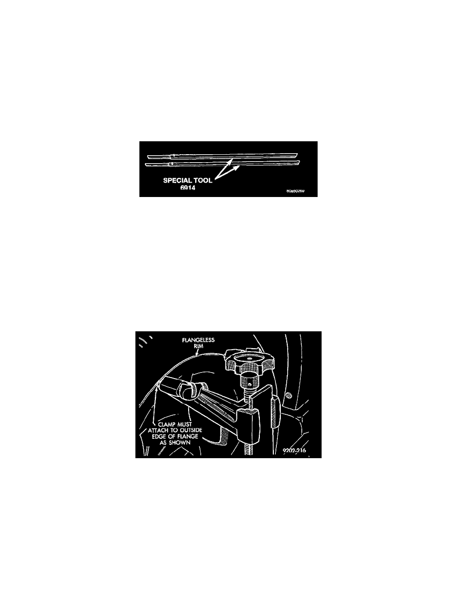
Vehicle Height Checking Fixtures
3. Install the front and rear Vehicle Height Checking Fixtures, Special Tools 6914, on the inner rim flange of the front and rear wheels and measure
vehicle curb height.
NOTE: If vehicle is within required curb height specification, proceed to step Step 4 of this procedure.
NOTE: If the vehicle is not within the required curb height specification range, do not perform a front or rear wheel alignment procedure at this
time. The vehicle MUST be within the required curb height specification to obtain an accurate wheel alignment.
Vehicle curb height on the Viper can be extremely affected If all rubber bushings used in the vehicles suspension are not tightened and torqued
with vehicle at specified design height. This is due to the extreme stiffness of the rubber bushings used in the vehicle's suspension components.
Refer to Setting Vehicle To Design Height in the Vehicle Height Adjustment.See: Vehicle Height Adjustment/Curb Height Checking and Setting
This will ensure all bushings are tightened and torqued to specifications, with the vehicle set to its specified design height. Then, recheck vehicle
curb height to verity it is within specification, before performing vehicle alignment procedure.
Alignment Equipment Head Attachment To Wheel
4. Attach alignment equipment heads onto the vehicle wheels. The Viper uses flangeless style wheels, thus any alignment equipment used must be
capable of attaching to outside edge of wheel rim lip.
5. Proceed with camber and caster angle adjustments.
CAMBER AND CASTER ANGLE ADJUSTMENT
The camber and caster angles on the Viper are adjustable using cams located on the lower control arm bushing pivot bolts. Correct camber and caster
specifications are obtained by simultaneously rotating front and rear adjustment cams until lower control arm is correctly positioned.
CAUTION: Prior to any cam bolt rotation, locknuts must be loosened to ends of pivot bolt threads. This must be done to allow lower control arm
mounting brackets to be spread, allowing free movement of bushings. If not done, serious bracket bending, weld breakage of cam retainer, free cam