
Summit L4-1795cc 1.8L SOHC (1995)
Ignition Control Module: Oscilloscope Patterns and Waveforms
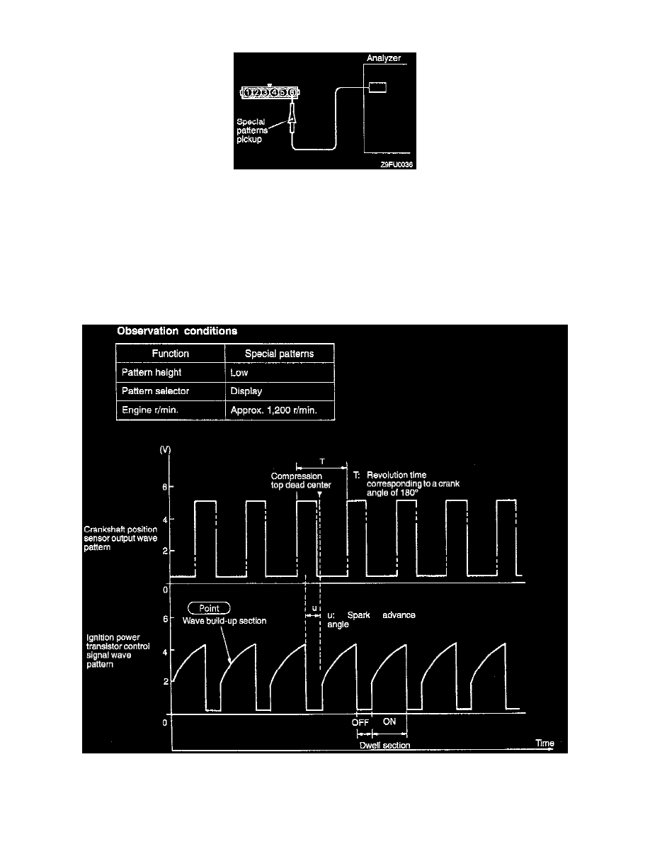
WAVE PATTERN INSPECTION USING AN ANALYZER
^
Ignition coil primary signal.
^
Ignition power transistor control signal
MEASUREMENT METHOD
1. Disconnect the ignition power transistor connector, and connect the special tool test harness: MB991348) in between. (All terminals should be
connected.)
2. Connect the analyzer special patterns pickup to ignition power transistor unit connector terminal No. 6.
ALTERNATE METHOD (test harness not available)
1. Connect the analyzer special patterns pickup to ECM terminal No. 10.
STANDARD WAVE PATTERN
WAVE PATTERN OBSERVATION POINTS
Condition of wave pattern build-up section and maximum voltage (Refer to abnormal wave pattern examples 1 and 2.)