
Summit Vista FWD L4-1795cc 1.8L SOHC (1992)
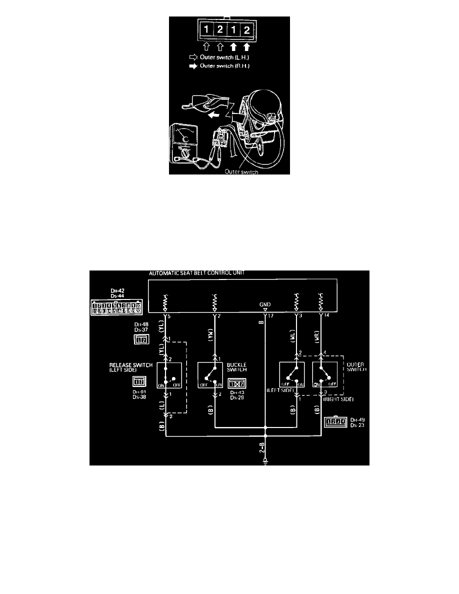
Fig. 8 Checking Outer Switch
1.
Disconnect the outer switch connector.
2.
Pull the shoulder belt out farther than its midpoint.
3.
Using a suitable ohmmeter, check continuity as shown.
4.
Continuity should be present with the belt pulled out past its midpoint.
5.
No continuity should be present when belt is pulled out less then its midpoint.
Release Switch (Driver's Side), Buckle & Release Switch
Fig. 125 Release Switch (driver's Side), Buckle Switch & Release Switch Circuit Diagram
1.
Check release switch (driver's side) circuit as follows:
a. Disconnect release switch harness connector.
b. Connect a suitable ohmmeter between release switch connector terminal 1 and ground.
c. Ohmmeter should indicate continuity.
d. If continuity is indicated, circuit is satisfactory. Proceed to step f.
e. If continuity is not indicated, repair harness as necessary.
f.
Connect release switch harness connector, then disconnect control unit harness connector.
g. Connect ohmmeter between control unit connector terminal 5 and ground.
h. Observe ohmmeter while moving slide anchor.
i.
Ohmmeter should indicate continuity when slide anchor is not in release (switch On) range.