
Talon FWD L4-1997cc 2.0L DOHC (1990)
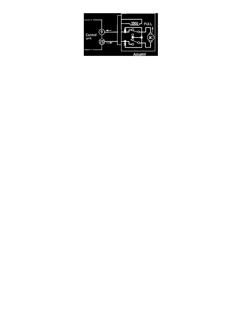
Fig. 95 Actuator Limit Switch
2. The indication of *1 shows the limit switch within the actuator becoming as shown. The actuator selector is at the fully closed position when the
resistance between terminals 9 and 20 is measured. For this reason, after checking polarity of the tester, the tester's probe should be connected so
current flows from terminal 20 to terminal 9.
3. For terminals indicated by the *2, it is necessary to check individual terminal voltages with the ECU's harness connector connected and the
ignition switch in the On position.