
Vision V6-3.5L VIN F (1997)
ABS Main Relay: Description and Operation
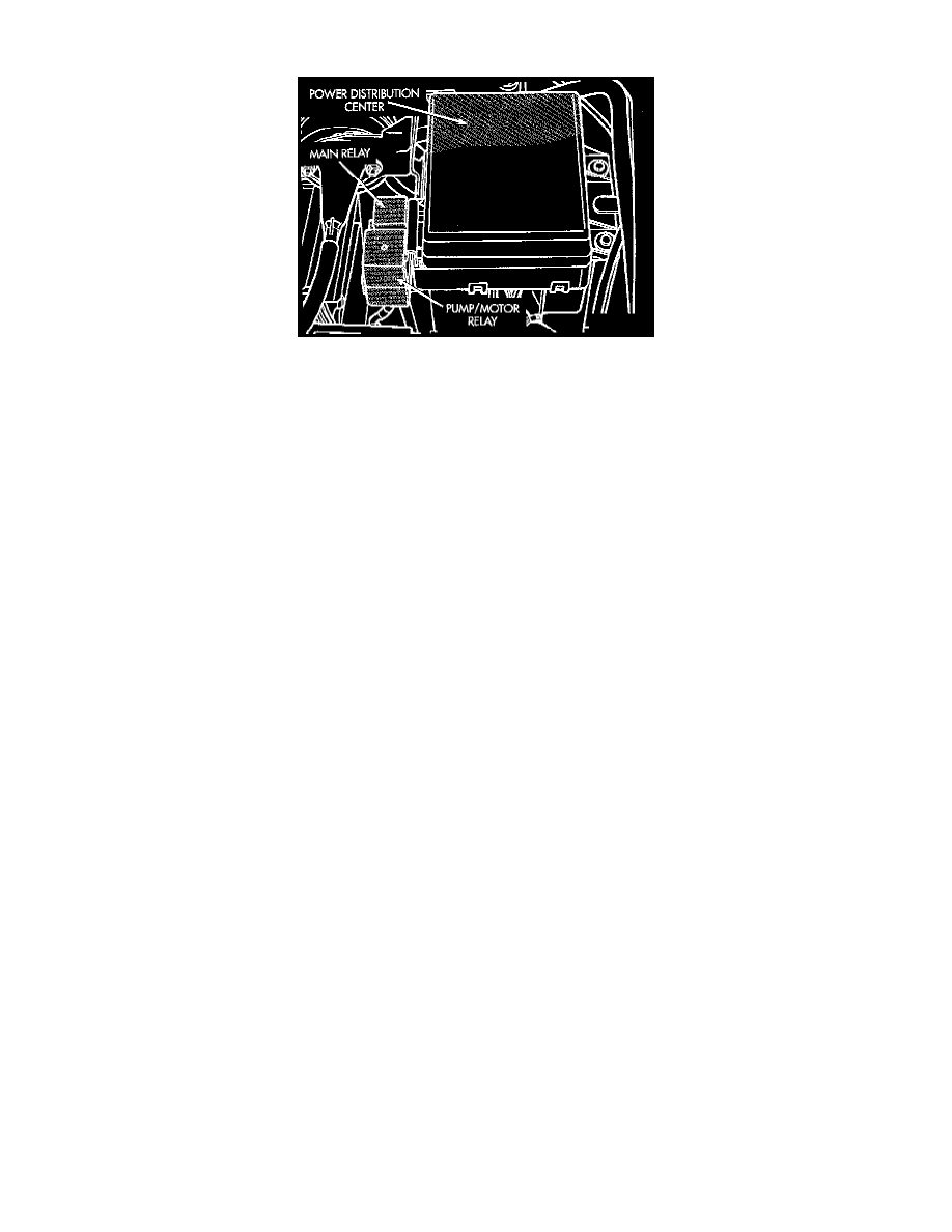
Main Relay And Pump/Motor Relay
MAIN RELAY
The Main Relay is attached to the outside of the Power Distribution Center PDC. The Main Relay has two functions. First, when the relay is
energized, it supplies power to the solenoid valves in the Valve Block Assembly and the pump/motor relay coil. Second, when the relay is
de-energized, it supplies a ground to turn on the ABS warning light. The Main Relay is controlled by the Controller Antilock Brake CAB. The
CAB energizes the Main Relay when it receives an ignition input signal and verifies that no locked faults exist.
PUMP/MOTOR RELAY
The Pump/Motor Relay supplies power to the pump/motor. It is attached to the outside of the PDC. The relay coil is powered by the Main Relay
and the coil ground is controlled by the CAB. The Pump/Motor Relay is a special four terminal relay and should not be replaced with a standard
relay. If either relay is defective both relays must be replaced. They are serviced as an assembly.
CIRCUIT OPERATION
The ABS main relay is used for the operation of the ABS system. Power for the coil side of the relay is supplied on circuit F20. This circuit is
protected by a 10 amp fuse located in cavity 6 of the junction block. Power for the fuse is supplied by circuit A22 from the ignition switch. This
circuit is HOT in the RUN position only
Power for the A22 circuit is supplied from the Power Distribution Center (PDC) on circuit A2. This circuit is protected by a 40 amp fuse located
in cavity J.
The ground side of the coil is controlled by the Controller Anti-Lock Brake (CAB) module on circuit B58. This circuit connects to cavity 32 of the
control module.
Circuit F20 is also spliced and provides an ignition input to the CAB.
Power for the contact side of the relay is supplied by circuit A20. This circuit is protected by a 30 amp fuse located in cavity I of the PDC. On
vehicles equipped with the optional traction control, circuit A20 is spliced and provides an input to the traction control portion of the CAB.
When the relay is energized, the relay moves from its normally grounded position to connect circuits A20 and B120. Circuit B120 is spliced and
provides three switched battery inputs to the CAB and power to the coil side of the ABS pump motor relay.
The relay is located on the PDC and is normally grounded in the OFF position. The ground is provided on circuit Z1 and terminates at the left
front frame rail.