
Bronco L6-300 4.9L VIN Y 1-bbl (1983)
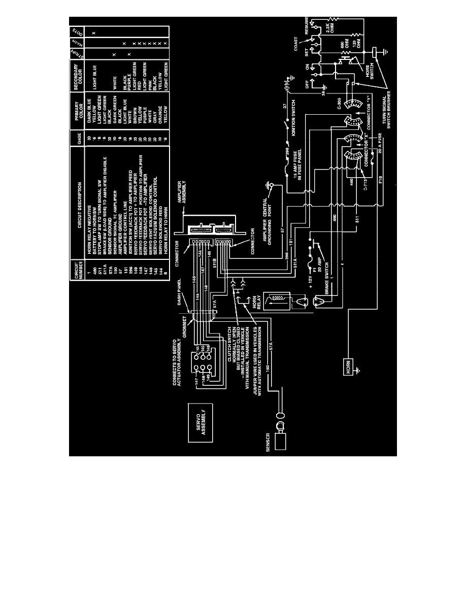
Fig. 5 Speed control wiring diagram. 1982---83 F-100-350, 1984---87 F-150-350 & 1982---87 Bronco
1981-87 Models Exc. 1983-87 Ranger, 1984-87 Bronco II & 1986-87 Aerostar
1.
Locate horn relay wire connector marked X and Y, Figs. 3, 4 and 5.
2.
Using connector X, locate wire 460, then using a suitable voltmeter, check for battery voltage at male side of connector.
3.
Using connector Y, locate wire 1, then using a suitable voltmeter, check for battery voltage at female side of connector. Depress horn, voltmeter
should read zero and horn should sound. If battery voltage remains, circuit is open. Connectors should remain connected during testing.
4.
Check horn relay by momentarily grounding circuit 1 to chassis. This bypasses horn switch and horn should sound. If horn does not sound, check
for battery voltage at connector X wire 6 during relay operation. If voltage is present at circuit 6 during relay operation, an open circuit is indicated
between horn and connector X.
5.
If relay does not operate with battery voltage present at circuit 460 and circuit 1 is grounded, replace relay.