
Bronco L6-300 4.9L VIN Y 1-bbl (1983)
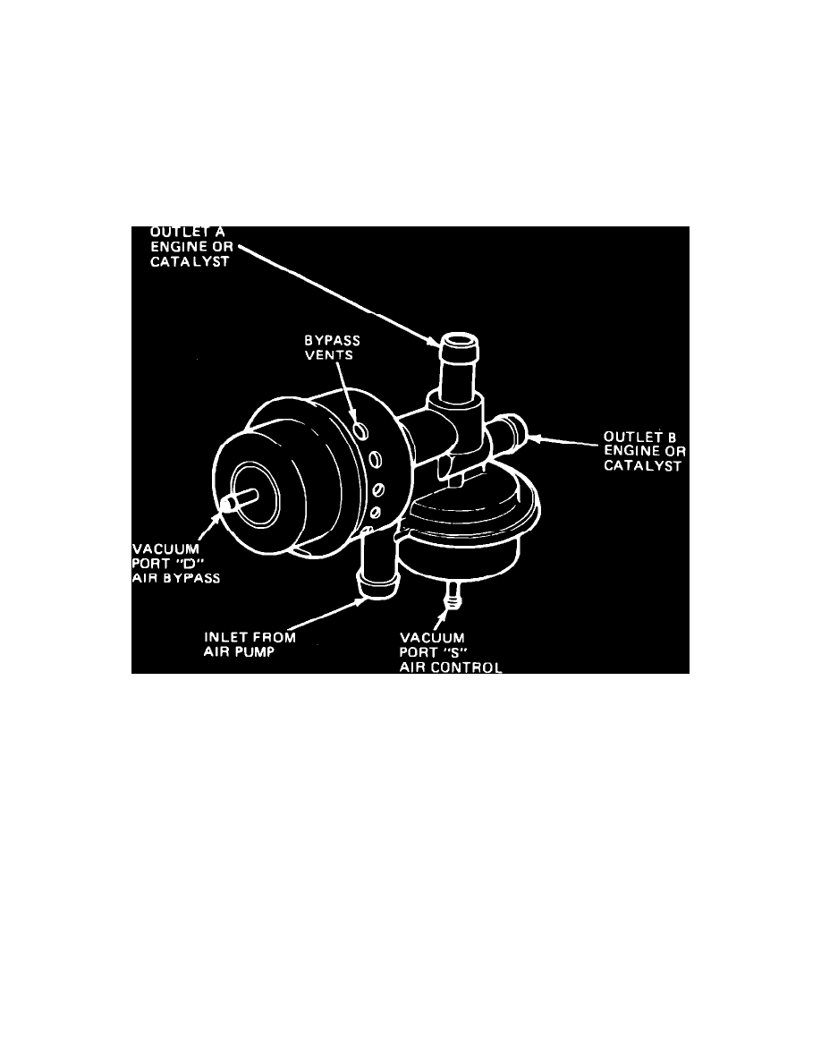
Fig. 72 Normally closed combination air bypass/air control valve with bleed
NORMALLY CLOSED VALVES
1.
Disconnect hoses from outlets A and B, Figs. 71 and 72.
2.
Disconnect and plug vacuum line to port D.
3.
Run engine at 1500 RPM. There should be air flow at bypass vents.
4.
Reconnect vacuum line to port D and disconnect and plug vacuum line to port S, then ensure that vacuum is present in line to vacuum port D.
5.
Run engine at 1500 RPM. There should be air flow at outlet B but no air flow at outlet A.
6.
Apply 8---10 inches Hg vacuum to port S and run engine at 1500 RPM. There should be air flow at outlet A.
7.
On bleed type valve, some lesser amount of air will flow from outlet A or B and the main discharge will change when vacuum is applied to port S.
If there is a small air tap attached to the inlet tube from the air pump, air flow should be present during engine operation.
Fig. 70 Normally open combination air bypass/air control valve less bleed
NORMALLY OPEN VALVES
1.
Disconnect hoses from outlets A and B, Fig. 70.
2.
Disconnect and plug vacuum lines to ports D and S.
3.
Run engine at 1500 RPM. There should be air flow at outlet B.
4.
Apply 8---10 inches Hg vacuum to port S and run engine at 1500 RPM. There should be air flow at outlet A.
5.
Reconnect vacuum line to port D and ensure that vacuum is present.
6.
Run engine at 1500 RPM. Air should flow out of bypass vents.
7.
Reconnect vacuum hoses to original positions.