
Bronco L6-300 4.9L VIN Y 1-bbl (1983)
2.
Attach negative (-) VOM, Rotunda Number 007-00001, lead to distributor base.
3.
Measure battery voltage.
4.
Attach VOM to small straight pin inserted into connector terminal No. 2.
CAUTION: Do not allow straight pin to contact electrical ground.
5.
Turn ignition switch to Run position and measure terminal No. 2 voltage.
6.
Turn ignition switch to Off position.
7.
Remove straight pin.
TEST RESULT
TEST RESOLUTION
90 percent of
^ Go to Part 2, Test 5.
battery voltage minimum
Less than 90
^ Go to Part 2, Test 9.
percent of battery voltage
Ignition Coil Primary Resistance
TFI-IV
Part 2
Test 3
TEST EQUIPMENT: VOM
TEST PROCEDURE
1.
Turn ignition switch to Off.
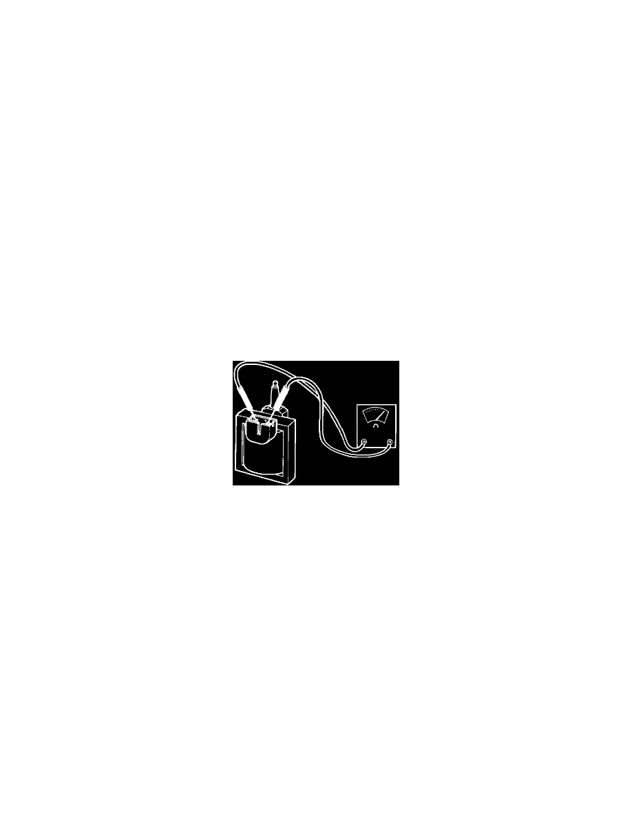
2.
Disconnect ignition coil connector. Inspect for dirt, corrosion, and damage.
3.
Measure resistance from positive (+) to negative (-) terminal of ignition coil, using Rotunda digital volt-ohmmeter 007-00001.
TEST RESULT
TEST RESOLUTION
0.3 to 1.0
^ Test result OK.
ohm
^ Go to Test 4.
Less than
^ Replace ignition coil.
0.3 ohm or greater than 1.0 ohm