
Bronco L6-300 4.9L VIN Y 1-bbl (1983)
Ignition Control Module: Description and Operation
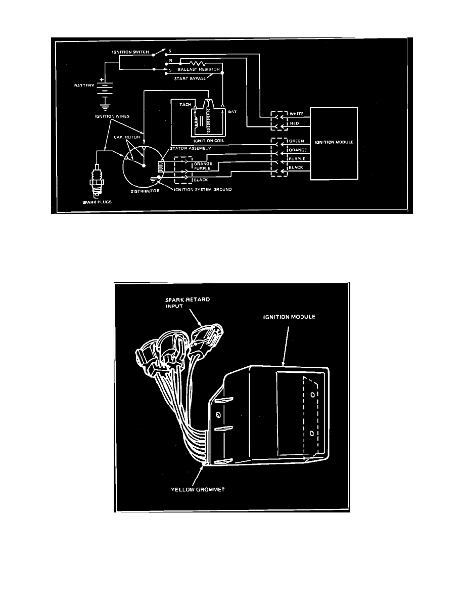
Typical Ignition System
The Ignition Module shuts off the primary circuit each time it receives a pulse from the magnetic pick-up Fig. 9. A timing circuit in the ignition module
turns the primary current back on after a short period of time. High voltage is created each time the magnetic field is built up and collapsed. The red
ignition module wire provides operating voltage for the module's electronic components in the Run mode. The white module wire and start bypass
provide increased voltage for the module and coil during Start mode.
Ignition Modules
Dura Spark II systems with UIM (Universal Ignition Module) Fig. 10 can respond to another control signal from either an Ignition Barometric Pressure
Switch, Ignition Timing Vacuum Switch, or the Microprocessor Control Unit (MCU), depending on the engine calibration. Responding to this second
signal, the UIM provides additional spark timing control for certain operating conditions by shutting off the ignition coil current flow at a different time
than with just the distributor pick-up signal.