
Bronco L6-300 4.9L VIN Y 1-bbl (1983)
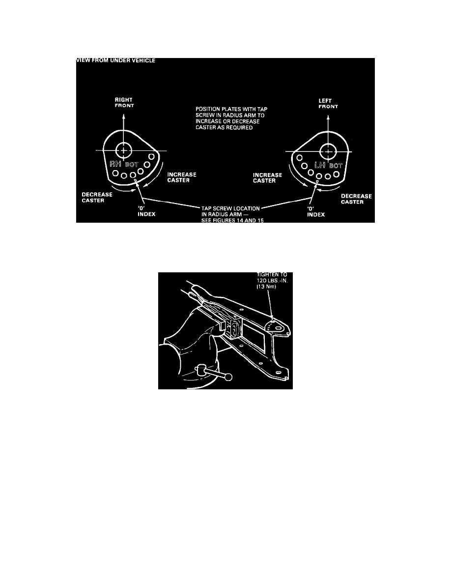
Figure 16 - Article 87-4-16
3.
With template secure, punch mark radius arm at the small hole in the template, as shown in Figures 14 and 15. Mark radius arm, and diegrind a
slot at the axle attaching hole the same size as the slot in the template, see Figure 16. De-burr the surface; avoid rounding the edges of the slot.
Figure 13 - Article 87-4-16
4.
Use a No. 6 drill to make a .204 inch diameter through hole at the punch mark. Line up the caster adjuster plate on the radius arm to obtain the
required change in caster, see Figure 13.
Figure 17 - Article 87-4-16
NOTE:
Each hole changes caster approximately 1/2 degree + or - from the "0" index hole.
5.
Install the tap screw to 120 in.lbs. (13 N-m) torque.
6.
Reinstall radius arm with a new bracket (front axle to radius arm). The new bracket has a larger "jaw" spacing to fit over caster adjuster plate.
^
For non-quad shock vehicles, install bracket E7TZ-3B446-A.
^
For quad shock vehicles, install bracket E7TZ-18112-A, R.H. or E7TZ-18113-A, L.H.