
Bronco L6-300 4.9L VIN Y 1-bbl (1983)
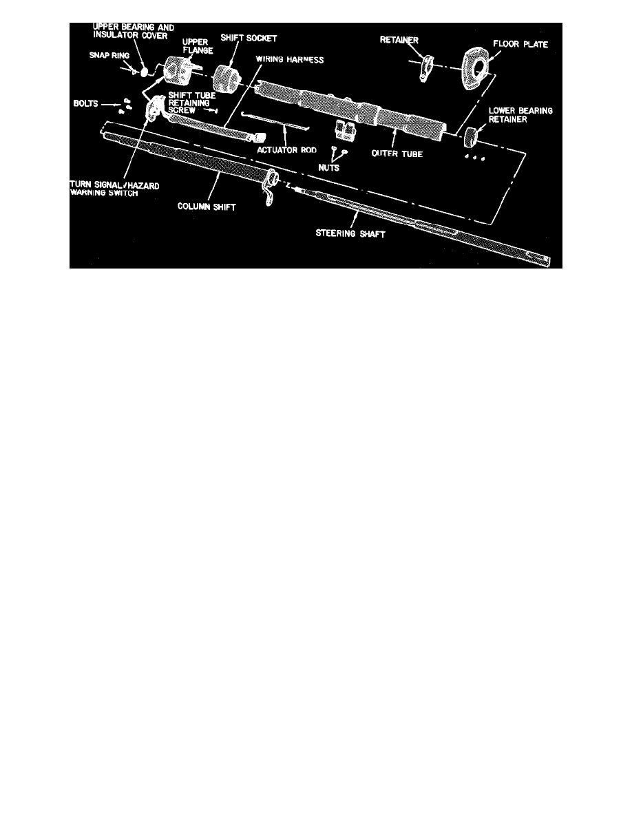
Fig. 3 Exploded view of non-tilt steering column. 1980---87 Bronco & F100-350 Series w/auto. trans.
1.
Remove turn signal lever.
2.
On vehicles equipped with 3 speed manual or automatic transmission, drive out pivot pin and remove hand shift lever.
3.
Partially withdraw turn signal/hazard warning switch, and key warning buzzer terminal if equipped, from upper flange, Figs. 1, 2 and 3.
4.
Remove snap ring from upper steering shaft.
5.
Remove lower bearing retainer from bottom of steering column.
6.
Using suitable tool, gently tap steering shaft out of bottom of steering column. Harsh impacts at either end of shaft may alter shaft in overall
length, adversely affecting assembly.
7.
On 1982 vehicles equipped with automatic transmission, remove shift tube retaining screw from bottom of shift socket.
8.
On 1983-87 vehicles equipped with automatic transmission, drill out shift tube retaining rivet from bottom of shift socket.
9.
On vehicles equipped with 3 speed manual or automatic transmission, withdraw shift tube assembly from bottom of column.
10.
On all vehicles, clip ignition switch in lock position and remove ignition switch and actuator rod.
11.
On E100-350 equipped with automatic transmission, remove PRNDL21 hood and lens assembly.
12.
On all vehicles, loosen upper flange retaining nuts until only 1 or 2 threads remain engaged, then pinch nuts toward each other and withdraw upper
flange from outer tube.
13.
On vehicles equipped with 3 speed manual or automatic transmission, remove shift socket from outer tube.
14.
On vehicles equipped with 4 speed manual transmission, remove flange extension from outer tube.
15.
Remove upper bearing and insulator cover from upper flange by gently tapping from opposite side.
16.
Remove flange retaining bolts and nuts.
17.
On vehicles with manual transmission, remove snap ring from lock release lever assembly.
18.
On vehicles equipped with manual transmission, remove lock release lever assembly through hole on front of flange and remove spring from
assembly.
19.
On vehicles equipped with automatic transmission, remove PRNDL21 insert from front of flange.
20.
On all vehicles, place lock cylinder in ``Run'' position and remove retaining pin, then remove lock cylinder from flange.