
Bronco L6-300 4.9L VIN Y 1-bbl (1983)
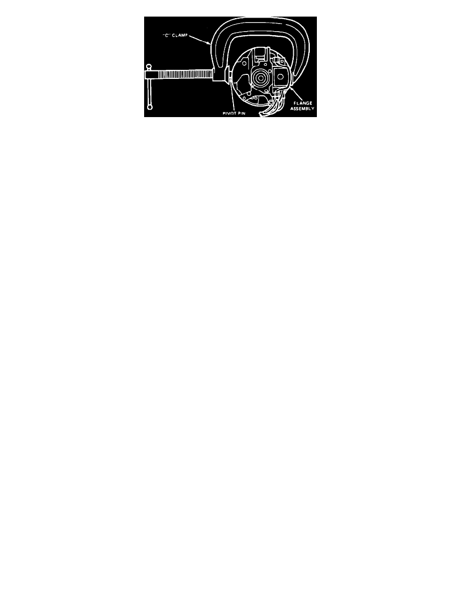
Fig. 6 Installing Flange Assembly Pivot Pins
1.
Position flange casting on suitable work bench with large bearing seat facing up.
2.
Place large upper bearing over seat with open side facing inward. Position a suitable socket on bearing outer race and lightly tap socket until
bearing is seated. Use care to avoid contacting bearing inner race as damage will result.
3.
Invert flange casting and repeat step 2 on small bearing.
4.
Install lower actuator with ignition switch rod attached.
5.
Install upper and lower flanges with pivot pins. Ensure column position spring is seated properly between upper and lower flange and wavy thrust
washer is properly positioned between lower flange and socket.
6.
Install column upper shaft snap ring.
7.
Install locking lever, spring and lever pin.
8.
Position wire bale on upper casting and install spring clips, Fig. 9.
9.
On models equipped with automatic transmission, install shift lever indicator ring on tilt mechanism. Torque attaching screws to 10-20 inch lbs.,
then install shift socket.
10.
On models equipped with manual transmission, attach key release mechanism to tilt mechanism, then install flange extension and torque attaching
screws to 10-20 inch lbs.
11.
On all models, install tilt mechanism. Feed steering shaft down center of column and ignition actuation rod through shift socket/flange extension
along top of column outer tube.
12.
Install flange retainer assemblies. Use new screws and torque to 50-68 inch lbs.
13.
Install lower bearing retainer, then loosely attach ignition switch to outer tube.
14.
Connect upper and lower actuators, then install column cover. Torque cover attaching screws to 40-50 inch lbs.
15.
Position turn signal switch and wiring harness in steering column. Attach wiring harness to steering column tube clips, if necessary.
16.
Install turn signal switch attaching screws and torque to 20-30 inch lbs.
17.
Install turn signal lever, then the lock drive gear.
18.
Install lock cylinder with key in ``On'' position. Ensure retaining pin is flush with cylinder.
19.
On models equipped with automatic transmission, install shift lever and pivot pin.
20.
On all models, install steering column.
1982-87 BRONCO, E100-350 & F100-350 SERIES, NON-TILT STEERING COLUMN