
Bronco L6-300 4.9L VIN Y 1-bbl (1983)
Axle Beam: Description and Operation
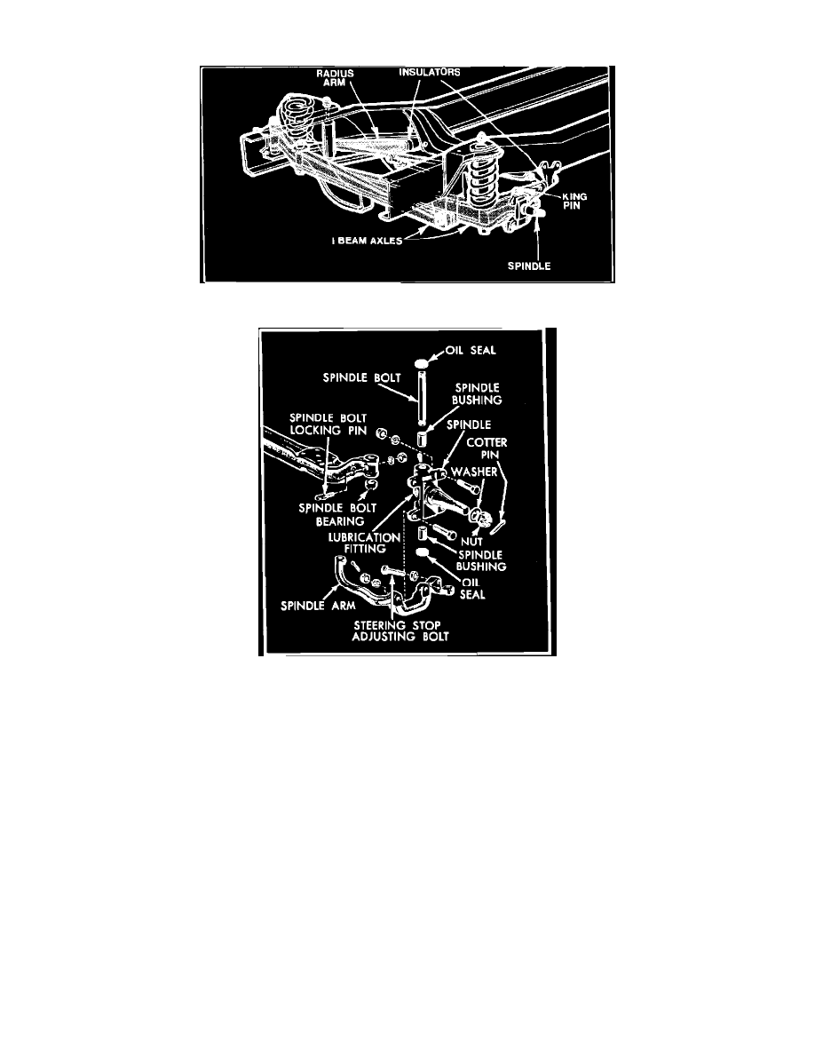
Fig. 1 Twin I-Beam front axle
Fig. 2 Spindle used with twin I Beam front axle. Typical
EXC. 4 WHEEL DRIVE MODELS
Twin I-Beam Axle
As illustrated in Fig. 1 there are two I-beam axles, one for each front wheel. One end of each axle is attached to the spindle and a radius arm and the
other end is attached to a frame bracket on the opposite side of the vehicle.
Each spindle is held in place on the axle by ball joints or a spindle bolt which pivots in bushings pressed in the upper and lower ends of the spindle,
Fig. 2. On models equipped with spindle bolts, a thrust bearing is installed between the lower end of the axle and the spindle to support the load on the
axle. On all models, a spindle arm is installed on each spindle for attachment to the steering linkage.