
Bronco L6-300 4.9L VIN Y 1-bbl (1983)
Pinion Bearing: Service and Repair
Dana/Spicer, Front Drive
Bearing Cup & Drive Pinion Installation, FRONT DRIVE
1.
Clean bore and if installed, remove the cup. Place oil baffle first and the required amount of shims in the inner pinion bearing bore and drive inner
pinion bearing cup in place.
2.
Place outer pinion cup into carrier and drive in place. Draw cups into the bore.
3.
Lubricate ends of outer pinion bearings rollers. Install outer bearing cone into place on the outer bearing cup.
4.
Install inner bearing cone and slinger onto pinion. Drive bearing on the pinion shaft until fully seated.
Drive Pinion Installation, DANA/SPICER, FRONT DRIVE
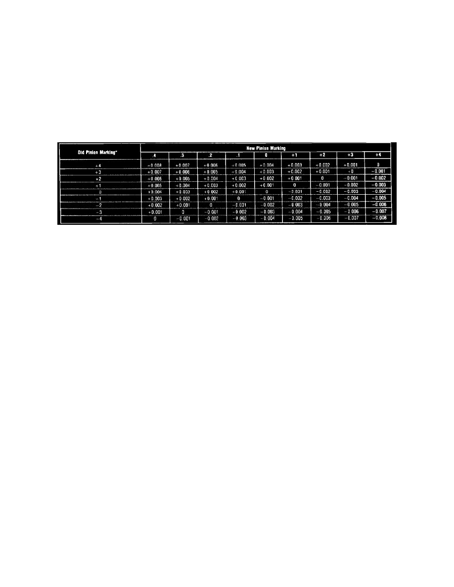
Fig. 7 Drive pinion adjusting shim thickness chart th gauge tool selection, model 44 & 50 axles
Two separate adjustments affect drive pinion and ring gear tooth contact. They are pinion depth (location) and backlash. The pinion locating shim pack
is installed between the drive pinion inner bearing cup and carrier housing. This shim pack and inner oil slinger and oil baffle, if equipped, controls the
position of the pinion. Adding shims moves the pinion toward the ring gear and removing shims moves the pinion away from the ring gear. Ring gears
and pinions are supplied in matched sets with the standard or metric markings. On the button of each drive pinion is marked a plus (+), a minus ( - ) or a
zero (0). These markings indicate the position for each gear set. The position is determined by the amount of shims between the inner pinion bearing cup
and carrier bearing bore. For example, if a new pinion is marked ``positive'' (+) +3 (+8-metric) and an old pinion is marked ``0'', shims measuring (.003
inch) (.08 mm) must be removed between the drive pinion and inner bearing cup and retainer. If the old ring and pinion shim is used, measure the slinger
and baffle and each shim separately and add each shim measurement to total the original measurement. If slinger and oil baffle is not used, install drive
pinion with the original shim pack and check pinion location with a suitable depth gauge. If a new ring and pinion is being installed, note the plus (+)
minus ( - ) or zero (0) marking on the bottom of the pinion assembly. Add or subtract shims, according to the chart to compensate for differences
between the old and new pinion. A new ring gear and drive pinion is always installed as a matched set and never separately. Ensure that the same
matching number appears on both the drive pinion and ring gear. Install the correct shim pack of the drive pinion and place the pinion into the carrier,
then check pinion depth. Refer to Fig. 7 for shim adjustment for pinion replacement and to ``Bearing Cup & Drive Pinion Installation'' to complete
procedure.
Drive Pinion Preload Check & Final Depth Check, FRONT DRIVE
1.
Measure original preload shims and replace with new shims of equal size.
2.
Install pinion into carrier.
3.
Install new preload shims over pinion. Install outer pinion bearing cone and oil slinger. Assemble end yoke, washer, deflector and slinger onto
pinion shaft and align assembly. Install a new pinion nut and torque to 200---220 ft. lbs. on except model 60 monobeam type axle or 240-300 ft.
lbs. on model 60 monobeam axle.
4.
Rotate pinion nut with an inch-pound torque wrench. Rotating torque should be 20---40 inch lbs. on except model 28 axle or 10 inch lbs. on model
28 axle. To increase preload, remove shims. To decrease preload, add shims.
5.
Install bearing caps and torque to 80---90 ft. lbs. on except model 28 axle or 35---40 ft. lbs. on model 28 axle.
6.
Install suitable final check gauge block onto top of the pinion button under the gauge tube. Place thumb on the gauge block to ensure block is
level.
7.
Insert feeler gauges between gauge tube and final check gauge block until a slight drag is felt.
8.
On except model 28 axles, the reading should be .020 inch added to the drive pinion etching, which could be plus (+) or minus ( - ) with a
tolerance of .002 inch. On model 28 axles (for example), if original pinion is etched (+) 4 (m + 10), and the new pinion is etched ``0'', then a new
selective slinger is .004 inch thicker than the original selective oil slinger. If the original pinion is ``0'' and the new pinion is etched (+) 3 (m + 8),
the new selective slinger should be .003 inch thinner than the original slinger.
9.
With drive pinion at the correct depth, remove yoke, washer and nut.
10.
Coat oil seal with suitable lubricant. Install drive pinion oil seal. After installation, ensure garter spring did not pop out. If garter spring pops out,
remove and replace seal.
11.
Install yoke. Install washer and nut. Tighten nut to 200---220 ft. lbs. on except model 60 monobeam axle or 240-300 ft. lbs on monobeam type
axle.