
Bronco L6-300 4.9L VIN Y 1-bbl (1983)
Note the 3/8 inch square drive in the handle to be used for obtaining the proper pinion bearing preload.
b. Center the proper gauge tube into the differential bearing bore. Install bearing caps. To preload the bearings, tighten handle to 20---40 inch
lbs.
c. Using a suitable feeler gauge tool or correct shims, select the thickest feeler shim that will enter between the gauge tube and gauge block.
Insert feeler gauge or shims directly along the gauge block to ensure a correct reading. The feeler gauge fit between the gauge tube and the
gauge block should be a slight drag-type feeling.
d. After the correct shims or feeler gauge feel is obtained, check reading and this is the thickness of shims required, providing that upon
inspection of the service pinion gear, there are no markings. If the service pinion gear is marked with a plus (+) reading, this amount
must be subtracted from the thickness dimension obtained previously.
e. If the service pinion gear is marked with a minus ( - ) reading, this amount must be added to the thickness dimension obtained previously.
f.
Measure shims to verify the shim size. Place oil slinger, if equipped, onto pinion and press on the bearing. If a baffle and/or slinger is used,
replace with a new one upon assembly and measure as part as the shim stack.
g. Continue to build the remaining components with proper pinion and differential bearing preload torques and ring gear backlash.
3.
On model 60 monobeam type axles proceed as follows:
a. Place a new inner pinion bearing over the proper aligning adapter and insert into pinion bearing retainer assembly. Place outer pinion bearing
(new or used, if in satisfactory condition) into bearing cup and assemble tool handle onto the screw. Hand tighten assembly. Note the 3/8 inch
square drive in the tool handle to be used for obtaining the proper pinion bearing preload. Torque to a 20-40 inch lb. preload.
b. Center proper gauge tube into the differential bearing bore. Install bearing caps and torque to 80-90 ft. lbs.
c. Using a feeler gauge tool or shims, select the thickest feeler gauge or shim that will enter between the gauge tube and block assembly. Insert
the feeler gauge directly along the gauge block to ensure a correct reading. The feeler gauge should have a slight drag-type feel. Ensure shims
or feeler gauge are free from dirt to ensure a correct reading.
d. After the correct feeler gauge feel has been obtained, check the reading. Reading obtained indicates the thickness of shims required
providing that, upon inspection of the service pinion gear, there are no markings. If the service pinion gear is marked with a (+) plus reading,
this amount must be subtracted from the thickness dimension obtained in step c.
e. If the service pinion gear is marked with a (-) minus reading, this amount must be added to the thickness dimension obtained in step c. In
addition, you must use the exact same new inner pinion bearing that was used in the previous steps.
f.
Remove inner pinion bearing cup and install the correct thickness of shims in the carrier bore. Install the bearing cup and oil slinger, if
equipped, onto pinion and press on the bearing assembly with tool T53T-4621-C or equivalent. If a baffle or oil slinger is used, replace with a
new one upon assembly and measure as part of the shim stack.
g. After following these procedures, continue to assemble the remaining components with proper pinion and differential bearing preload
torques and ring gear backlash.
Drive Pinion Installation, DANA/SPICER FRONT AXLE
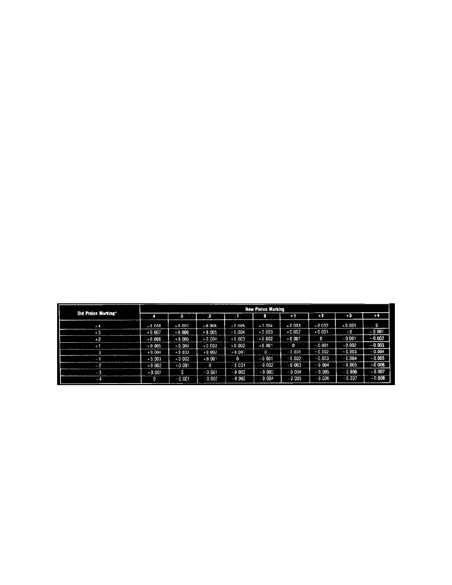
Fig. 7 Drive pinion adjusting shim thickness chart th gauge tool selection, model 44 & 50 axles
Two separate adjustments affect drive pinion and ring gear tooth contact. They are pinion depth (location) and backlash. The pinion locating shim pack
is installed between the drive pinion inner bearing cup and carrier housing. This shim pack and inner oil slinger and oil baffle, if equipped, controls the
position of the pinion. Adding shims moves the pinion toward the ring gear and removing shims moves the pinion away from the ring gear. Ring gears
and pinions are supplied in matched sets with the standard or metric markings. On the button of each drive pinion is marked a plus (+), a minus ( - ) or a
zero (0). These markings indicate the position for each gear set. The position is determined by the amount of shims between the inner pinion bearing cup
and carrier bearing bore. For example, if a new pinion is marked ``positive'' (+) +3 (+8-metric) and an old pinion is marked ``0'', shims measuring (.003
inch) (.08 mm) must be removed between the drive pinion and inner bearing cup and retainer. If the old ring and pinion shim is used, measure the slinger
and baffle and each shim separately and add each shim measurement to total the original measurement. If slinger and oil baffle is not used, install drive
pinion with the original shim pack and check pinion location with a suitable depth gauge. If a new ring and pinion is being installed, note the plus (+)
minus ( - ) or zero (0) marking on the bottom of the pinion assembly. Add or subtract shims, according to the chart to compensate for differences
between the old and new pinion. A new ring gear and drive pinion is always installed as a matched set and never separately. Ensure that the same
matching number appears on both the drive pinion and ring gear. Install the correct shim pack of the drive pinion and place the pinion into the carrier,
then check pinion depth. Refer to Fig. 7 for shim adjustment for pinion replacement and to ``Bearing Cup & Drive Pinion Installation'' to complete
procedure.
Drive Pinion Preload Check & Final Depth Check Front Drive
1.
Measure original preload shims and replace with new shims of equal size.