| Diagnosis and Testing Worldwide diagnostic system (WDS) Inspection and Verification - Verify the customer concern.
- Visually inspect for obvious signs of mechanical or electrical damage.
Visual Inspection Chart | Mechanical | Electrical | - Parking brake switch
- Parking brake cable(s)
| - Parking brake switch
- Clutch pedal switch
- Fuse(s)
- Circuits
| - If an obvious cause for an observed or reported concern is found, correct the cause (if possible) before proceeding to the next step.
- If the cause is not visually evident, retrieve the DTCs and refer to the symptom chart.
Symptom Chart Symptom Chart | Symptom | Possible Sources | Action | | The parking brake will not apply | * Rear brake calipers. * Parking brake cable(s). | * | | * Parking brake switch. * Battery. * Parking brake module. | * REFER to WDS. | | The parking brake will not release | * Parking brake switch. * Parking brake cable(s). * Clutch pedal switch. * Brake pedal position switch. | * | | * Parking brake switch. * Battery. * Parking brake module. | * REFER to WDS. | | DTC B1317: Battery voltage high | * Charging system. | * Check the charging system.
REFER to: Charging System (414-00 Charging System - General Information, Diagnosis and Testing).
REPEAT the self-test, CLEAR the DTCs. | | DTC B1318: Battery voltage low | * Battery. * Charging system. * Circuit. | * | | DTC B1342: Electronic parking brake module is faulty | * Parking brake module. | * | | DTC B1353: Ignition key-in circuit open | * Ignition switch. * Circuit. | * | | DTC B2477: Module configuration failure | * Parking brake module. | * Configure the parking brake module.
REFER to: Module Configuration (418-01 Module Configuration, General Procedures).
REPEAT the self-test, CLEAR the DTCs. | | DTC B2992: Electronic parking brake overload | * Parking brake module. | * | | DTC B2993: Electronic parking brake module temperature too high | * Parking brake module. | * | | DTC B2994: Electronic parking brake temperature sensor too high | * Parking brake module. | * | | DTC C1305: Longitudinal accelerometer signal fault | * Parking brake module. | * Re-calibrate the longitudinal accelerometer. REFER to WDS. REPEAT the self-test, CLEAR the DTCs. If the DTC occurs again, INSTALL a new parking brake module.
REFER to: Parking Brake Module (206-05 Parking Brake and Actuation, Removal and Installation).
| | DTC C1519: Fault warning indicator circuit failure | * Parking brake switch. * Circuit(s). | * | | DTC C1730: Reference voltage out of range (+5v) | * Parking brake module. | * | | DTC C1821: Electronic parking brake motor failure | * Parking brake module. | * | | DTC C1822: Electronic parking brake sensor electrical failure | * Parking brake module. | * | | DTC C1823: Electronic parking brake sensor signal failure | * Parking brake module. | * | | DTC C1826: Electronic parking brake electrical failure | * Parking brake module. | * | | DTC C1827: Electronic parking brake switch defective | * Parking brake switch. * Circuit(s). | * | | DTC C1828: Electronic parking brake force sensor not calibrated | * Parking brake module. | * | | DTC C1829: Electronic parking brake switch not connected | * Parking brake switch. | * Make sure the parking brake switch is connected. REPEAT the self-test, CLEAR the DTCs. | | * Circuit(s). | * | | DTC C2769: Longitudinal acceleration sensor electrical failure | * Parking brake module. | * | | DTC C2785: Sensor(s) out of calibration | * Longitudinal acceleration sensor. | * Initialize the longitudinal acceleration sensor. REFER to WDS. REPEAT the self-test, CLEAR the DTCs. | | DTC P1628: Electronic parking brake module ignition supply circuit open | * Circuit. | * | | DTC U0073: CAN module communication bus off | * Circuit(s). | * | | DTC U1900: CAN communication bus fault – Receiver error | * Powertrain control module. | * Check the electronic engine controls.
REFER to: Electronic Engine Controls (303-14 Electronic Engine Controls, Diagnosis and Testing).
REPEAT the self-test, CLEAR the DTCs. | | * ABS/ESP control module. | * Check the ABS/ESP control module.
REFER to: Anti-Lock Control (206-09A Anti-Lock Control, Diagnosis and Testing).
REPEAT the self-test, CLEAR the DTCs. | | * Instrument Cluster. | * Check the instrument cluster.
REFER to: Instrument Cluster (413-01 Instrument Cluster, Diagnosis and Testing).
REPEAT the self-test, CLEAR the DTCs. | | * Transmission control module. | * Check the automatic transmission control module. REFER to WDS. REPEAT the self-test, CLEAR the DTCs. | | * Circuit(s). | * CHECK the CAN bus,
REFER to: Communications Network (418-00 Module Communications Network, Diagnosis and Testing).
REPEAT the self-test, CLEAR the DTCs. | | DTC U2023: Fault received from external node | * ABS/ESP control module. | * Check the ABS/ESP control module.
REFER to: Anti-Lock Control (206-09A Anti-Lock Control, Diagnosis and Testing).
REPEAT the self-test, CLEAR the DTCs. | | * Instrument Cluster. | * Check the instrument cluster.
REFER to: Instrument Cluster (413-01 Instrument Cluster, Diagnosis and Testing).
REPEAT the self-test, CLEAR the DTCs. | | * Transmission control module. | * Check the automatic transmission control module. REFER to WDS. REPEAT the self-test, CLEAR the DTCs. | | * Powertrain control module. * Circuit(s). | * Check the CAN bus modules.
REFER to: Communications Network (418-00 Module Communications Network, Diagnosis and Testing).
REPEAT the self-test, CLEAR the DTCs. | | Electronic parking brake module internal failure. | * Parking brake module | * | Pinpoint Tests | PINPOINT TEST A : THE PARKING BRAKE WILL NOT APPLY | | TEST CONDITIONS | DETAILS/RESULTS/ACTIONS | | A1: CHECK THE OPERATION OF THE PARKING BRAKE CABLES | | | 1 With the aid of another technician, operate the parking brake switch and check the operation of the parking brake cables. | | | Do the parking brake cables operate correctly? Yes No REFER to WDS. | | A2: CHECK FOR WORN REAR BRAKE PADS AND DISCS | | | 1 Inspect the rear brake pads and discs.
REFER to: Specifications (206-05 Parking Brake and Actuation, Specifications).
| | | Are the rear brake pads and rear brake discs OK? Yes VERIFY the customer concern. No INSTALL new rear brake pads and rear brake discs as necessary. REFER to: (206-04 ) Brake Pads (Removal and Installation), Brake Disc (Removal and Installation). REPEAT the self-test, CLEAR the DTCs. | | PINPOINT TEST B : THE PARKING BRAKE WILL NOT RELEASE | | TEST CONDITIONS | DETAILS/RESULTS/ACTIONS | | B1: CHECK THE PARKING BRAKE OPERATION WITH THE BRAKE PEDAL APPLIED | | | 1 Apply the parking brake. | | | 2 Raise and support the vehicle.
REFER to: Jacking (100-02 Jacking and Lifting, Description and Operation) /
Lifting (100-02 Jacking and Lifting, Description and Operation).
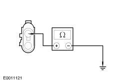
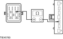
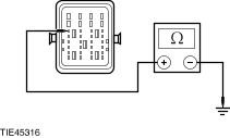
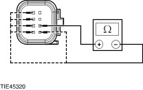
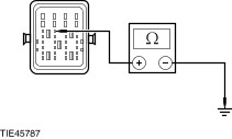
| | | 3 Ignition switch in position II. | | | 4 Release the parking brake by depressing the brake pedal and pressing down the parking brake switch. With the aid of another technician, check the operation of the parking brake. | | | Does the parking brake release? Yes No | | B2: CHECK THE PARKING BRAKE OPERATION WITH THE CLUTCH PEDAL APPLIED | | | 1 Apply the parking brake. | | | 2 Release the parking brake by depressing the clutch pedal and pressing down the parking brake switch. With the aid of another technician, check the operation of the parking brake. | | | Does the parking brake release? Yes REFER to WDS. No | | B3: CHECK THE PARKING BRAKE CABLES | | | 1 Release the parking brake by depressing the brake pedal and pressing down the parking brake switch. With the aid of another technician, check the operation of the parking brake. | | | Do the parking brake cables release? Yes CHECK the brake system components. REPAIR or INSTALL new components as necessary. REFER to: Parking Brake Cable (206-05, Removal and Installation), Brake Caliper (206-04 Rear Disc Brake, Removal and Installation), Brake Pads (206-04 Rear Disc Brake, Removal and Installation). REPEAT the self-test, CLEAR the DTCs. No | | B4: CHECK THE CLUTCH PEDAL SWITCH | | | 1 Using WDS, check the instrument cluster for clutch pedal switch DTCs. | | | Are any clutch pedal switch DTCs present? Yes No | | B5: CHECK THE CLUTCH PEDAL SWITCH GROUND CIRCUIT | | | 1 Ignition switch in position 0. | | | 2 Disconnect Clutch Pedal Switch C825. | | | 3 Measure the resistance between the clutch pedal switch C825 pin 3, circuit 91-BB6 (BK/YE), harness side and ground. | | | Is the resistance less than 5 ohms? Yes No REPAIR circuit 91-BB6 (BK/YE). REPEAT the self-test, CLEAR the DTCs. | | B6: CHECK FOR CONTINUITY BETWEEN THE INSTRUMENT CLUSTER AND THE CLUTCH PEDAL SWITCH CIRCUIT | | | 1 Disconnect Instrument Cluster C809. | | | 2 Measure the resistance between the instrument cluster C809 pin 10, circuit 91S-BB6 (BK/YE), harness side and the clutch pedal switch C825 pin 2, circuit 91S-BB6 (BK/YE), harness side. | | | Is the resistance less than 5 ohms? Yes INSTALL a new clutch pedal switch. REPEAT the self-test, CLEAR the DTCs. No REPAIR circuit 91S-BB6 (BK/YE). REPEAT the self-test, CLEAR the DTCs. | | B7: CHECK THE PARKING BRAKE PEDAL SWITCH | | | 1 Using WDS, check the instrument cluster for brake pedal switch DTCs. | | | Are any brake pedal switch DTCs present? Yes No | | B8: CHECK THE BRAKE PEDAL SWITCH GROUND CIRCUIT | | | 1 Ignition switch in position 0. | | | 2 Disconnect Brake Pedal Switch C824. | | | 3 Measure the resistance between the brake pedal switch C824 pin 2, circuit 91-PG6 (BK/YE), harness side and ground. | | | Is the resistance less than 5 ohms? Yes No REPAIR circuit 91-PG6 (BK/YE). REPEAT the self-test, CLEAR the DTCs. | | B9: CHECK FOR CONTINUITY BETWEEN THE INSTRUMENT CLUSTER AND THE BRAKE PEDAL SWITCH CIRCUIT | | | 1 Disconnect Instrument Cluster C809. | | | 2 Measure the resistance between the instrument cluster C809 pin 29, circuit 91S-PG6 (BK/YE), harness side and the brake pedal switch C824 pin 1, circuit 91S-PG6 (BK/YE), harness side. | | | Is the resistance less than 5 ohms? Yes INSTALL a new brake pedal switch. REPEAT the self-test, CLEAR the DTCs. No REPAIR circuit 91S-PG6 (BK/YE). REPEAT the self-test, CLEAR the DTCs. | | B10: CHECK THE CLUTCH PEDAL SWITCH CIRCUIT | | | 1 Ignition switch in position 0. | | | 2 Disconnect Parking Brake Module C883. | | | 3 Depress and hold the clutch pedal. | | | 4 Measure the resistance between the parking brake module C883 pin C2, circuit 91S-CG15 (BK/OG), harness side and ground. | | | Is the resistance less than 5 ohms? Yes No | | B11: CHECK THE CLUTCH PEDAL SWITCH CIRCUIT (CONTINUED) | | | 1 Disconnect Clutch Pedal Switch C863. | | | 2 Measure the resistance between the parking brake module C883 pin C2, circuit 91S-CG15 (BK/OG), harness side and ground. | | | Is the resistance less than 5 ohms? Yes REPAIR circuit 91S-CG15 (BK/OG). REPEAT the self-test, CLEAR the DTCs. No INSTALL a new parking brake module.
REFER to: Parking Brake Module (206-05 Parking Brake and Actuation, Removal and Installation).
REPEAT the self-test, CLEAR the DTCs. | | B12: CHECK THE BRAKE PEDAL SWITCH | | | 1 Using WDS, check the powertrain control module for any brake pedal switch DTCs. | | | Are any brake pedal switch DTCs present? Yes REFER to WDS. No | | B13: CHECK THE STOP LAMP CIRCUIT | | | 1 Ignition switch in position II. | | | 2 Depress the brake pedal. | | | Do the stop lamps illuminate? Yes REPAIR circuit 15S-LG23 (GN/WH). REPEAT the self-test, CLEAR the DTCs. No CHECK the stop lamp circuit.
REFER to: Stoplamps (417-01 Exterior Lighting, Diagnosis and Testing).
REPEAT the self-test, CLEAR the DTCs. | | B14: CHECK THE CLUTCH PEDAL SWITCH CIRCUIT (CONTINUED) | | | 1 Disconnect Clutch Pedal Switch C863. | | | 2 Measure the resistance between the parking brake module C883 pin C2, circuit 91S-CG15 (BK/OG), harness side and the clutch pedal switch C863 pin 1, circuit 91S-CG15 (BK/OG), harness side. | | | Is the resistance less than 5 ohms? Yes No REPAIR circuit 91S-CG15 (BK/OG). REPEAT the self-test, CLEAR the DTCs. | | B15: CHECK THE CLUTCH PEDAL SWITCH CIRCUIT (CONTINUED) | | | 1 Measure the resistance between the clutch pedal switch C863 pin 2, circuit 91-CG15 (BK/OG), harness side and ground. | | | Is the resistance less than 5 ohms? Yes INSTALL a new clutch pedal switch. REPEAT the self-test, CLEAR the DTCs. No REPAIR circuit 91-CG15 (BK/OG). REPEAT the self-test, CLEAR the DTCs. | | PINPOINT TEST C : DTC B1318: BATTERY VOLTAGE LOW | | TEST CONDITIONS | DETAILS/RESULTS/ACTIONS | | C1: CHECK THE BATTERY VOLTAGE | | | 1 Ignition switch in position III. | | | 2 Ignition switch in position II. | | | 3 Check the battery voltage. | | | Is the voltage greater than 10 volts? Yes No CHECK the battery and charging system.
REFER to: Charging System (414-00 Charging System - General Information, Diagnosis and Testing).
REPEAT the self-test, CLEAR the DTCs. | | C2: CHECK FOR VOLTAGE TO THE PARKING BRAKE MODULE | | | 1 Ignition switch in position 0. | | | 2 Disconnect Parking Brake Module C883. | | | 3 Measure the voltage between the: - parking brake module C883 pin G4, circuit 30-CG16A (RD), harness side and ground.
- parking brake module C883 pin H4, circuit 30-CG16B (RD), harness side and ground.
| | | Are the voltages greater than 10 volts? Yes No REPAIR circuit 30-CG16 (RD) or circuit 30-CG16A (RD) or circuit 30-CG16B (RD). REPEAT the self-test, CLEAR the DTCs. | | C3: CHECK FOR CONTINUITY BETWEEN THE BATTERY JUNCTION BOX (BJB) AND THE PARKING BRAKE MODULE | | | 1 Disconnect Fuse 17 (30A). | | | 2 Measure the resistance between the BJB fuse 17 (30A), harness side and the parking brake module C883 pin G4, circuit 30-CG16A (RD), harness side. | | | Is the resistance less than 5 ohms? Yes CLEAR the DTCs, REPEAT the self-test. If the DTC remains, INSTALL a new parking brake module.
REFER to: Parking Brake Module (206-05 Parking Brake and Actuation, Removal and Installation).
REPEAT the self-test, CLEAR the DTCs. No REPAIR circuit 30-CG16 (RD) or circuit 30-CG16A (RD) or circuit 30-CG16B (RD). REPEAT the self-test, CLEAR the DTCs. | | PINPOINT TEST D : DTC B1353: IGNITION KEY-IN CIRCUIT OPEN | | TEST CONDITIONS | DETAILS/RESULTS/ACTIONS | | D1: CHECK FOR VOLTAGE TO THE PARKING BRAKE MODULE | | | 1 Disconnect Parking Brake Module C883. | | | 2 Ignition key in ignition. | | | 3 Measure the voltage between the parking brake module C883 pin F2, circuit 30S-CG16A (RD/BU), harness side and ground. | | | Is the voltage greater than 10 volts? Yes CLEAR the DTCs, REPEAT the self-test. If the DTC remains, INSTALL a new parking brake module.
REFER to: Parking Brake Module (206-05 Parking Brake and Actuation, Removal and Installation).
REPEAT the self-test, CLEAR the DTCs. No | | D2: CHECK FOR CONTINUITY BETWEEN THE IGNITION SWITCH AND THE PARKING BRAKE MODULE | | | 1 Remove the ignition key. | | | 2 Disconnect Ignition Switch C456. | | | 3 Measure the resistance between the parking brake module C883 pin F2, circuit 30S-CG16A (RD/BU), harness side and the ignition switch C456 pin 5, circuit 30S-CG16A (RD/BU), harness side. | | | Is the resistance less than 5 ohms? Yes No REPAIR circuit 30S-CG16A (RD/BU). REPEAT the self-test, CLEAR the DTCs. | | D3: CHECK THE PARKING BRAKE MODULE IGNITION CIRCUIT FOR A SHORT TO GROUND | | | 1 Measure the resistance between the parking brake module C883 pin F2, circuit 30S-CG16A (RD/BU), harness side and ground. | | | Is the resistance greater than 10,000 ohms? Yes INSTALL a new ignition switch.
REFER to: Ignition Switch (211-05 Steering Column Switches, Removal and Installation).
REPEAT the self-test, CLEAR the DTCs. No REPAIR circuit 30S-CG16A (RD/BU). REPEAT the self-test, CLEAR the DTCs. | | PINPOINT TEST E : DTC B2992: ELECTRONIC PARKING BRAKE OVERLOAD; DTC B2993: ELECTRONIC PARKING BRAKE MODULE TEMPERATURE TOO HIGH; DTC B2994: ELECTRONIC PARKING BRAKE TEMPERATURE SENSOR TOO HIGH | NOTE:The ignition key must be installed in the ignition switch and the electronic parking brake must not be operated for 15 minutes before carrying out this pinpoint test. | NOTE:The ignition key must be installed in the ignition switch at all times during this pinpoint test. | | TEST CONDITIONS | DETAILS/RESULTS/ACTIONS | | E1: INITIALIZE THE PARKING BRAKE MODULE | | | 1 Ignition switch in position 0. | | | 2 Disconnect the battery ground cable,
REFER to: Battery Disconnect (414-01 Battery, Mounting and Cables, General Procedures).
| | | 3 Wait for one minute. | | | 4 Connect the battery ground cable,
REFER to: Battery Disconnect (414-01 Battery, Mounting and Cables, General Procedures).
| | | 5 Ignition switch in position II. | | | 6 Clear the DTCs. | | | 7 Apply the parking brake. | | | Does the parking brake operate correctly? Yes No READ the DTCs and REFER to the symptom chart. | | E2: INITIALIZE THE PARKING BRAKE MODULE (CONTINUED) | | | 1 Release the parking brake. | | | 2 Read the DTCs. | | | Are any DTCs still present? Yes INSTALL a new parking brake module.
REFER to: Parking Brake Module (206-05 Parking Brake and Actuation, Removal and Installation).
REPEAT the self-test, CLEAR the DTCs. No CARRY OUT a road test. REPEAT the self-test, CLEAR the DTCs. | | PINPOINT TEST F : DTC C1519: FAULT WARNING INDICATOR CIRCUIT FAILURE | | TEST CONDITIONS | DETAILS/RESULTS/ACTIONS | | F1: CHECK THE PARKING BRAKE MODULE CIRCUIT FOR A SHORT TO BATTERY | | | 1 Disconnect Parking Brake Module C883. | | | 2 Disconnect Central Junction Box C103. | | | 3 Measure the voltage between the parking brake module C883 pin F4, circuit 31S-CG16 (BK/BU), harness side and ground. | | | Is any voltage present? Yes REPAIR circuit 31S-CG16 (BK/BU). REPEAT the self-test, CLEAR the DTCs. No | | F2: CHECK FOR CONTINUITY BETWEEN THE PARKING BRAKE MODULE AND THE PARKING BRAKE SWITCH | | | 1 Disconnect Parking Brake Switch C930. | | | 2 Measure the resistance between the parking brake module C883 pin F4, circuit 31S-CG16 (BK/BU), harness side and the parking brake switch C930 pin 1, circuit 31S-CG16 (BK/BU), harness side. | | | Is the resistance less than 5 ohms? Yes No REPAIR circuit 31S-CG16 (BK/BU). REPEAT the self-test, CLEAR the DTCs. | | F3: CHECK FOR CONTINUITY BETWEEN THE CENTRAL JUNCTION BOX (CJB) AND THE PARKING BRAKE SWITCH | | | 1 Measure the resistance between the CJB C103 pin 6, circuit 31S-GE44 (BK/RD), harness side and the parking brake switch C930 pin 1, circuit 31S-GE44 (BK/RD), harness side. | | | Is the resistance less than 5 ohms? Yes No REPAIR circuit 31S-GE44 (BK/RD). REPEAT the self-test, CLEAR the DTCs. | | F4: CHECK THE PARKING BRAKE MODULE FOR A SHORT TO GROUND | | | 1 Measure the resistance between the parking brake module C883 pin F4, circuit 31S-CG16 (BK/BU), harness side and ground. | | | Is the resistance greater than 10,000 ohms? Yes INSTALL a new parking brake module.
REFER to: Parking Brake Module (206-05 Parking Brake and Actuation, Removal and Installation).
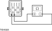
REPEAT the self-test, CLEAR the DTCs. No REPAIR circuit 31S-CG16 (BK/BU). REPEAT the self-test, CLEAR the DTCs. | | PINPOINT TEST G : DTC C1827: ELECTRONIC PARKING BRAKE SWITCH DEFECTIVE | | TEST CONDITIONS | DETAILS/RESULTS/ACTIONS | | G1: CHECK FOR CONTINUITY BETWEEN THE PARKING BRAKE MODULE AND THE PARKING BRAKE SWITCH | | | 1 Disconnect Parking Brake Switch C909. | | | 2 Disconnect Parking Brake Module C883. | | | 3 Measure the resistance between the: - parking brake module C883 pin B3, circuit 7-CG15 (YE/BU), harness side and the parking brake switch C909 pin 3, circuit 7-CG15 (YE/BU), harness side.
- parking brake module C883 pin B4, circuit 10-CG15 (GY/VT), harness side and the parking brake switch C909 pin 4, circuit 10-CG15 (GY/VT), harness side.
| | | Are the resistances less than 5 ohms? Yes No REPAIR circuit 7-CG15 (YE/BU) or circuit 10-CG15 (GY/VT). REPEAT the self-test, CLEAR the DTCs. | | G2: CHECK FOR CONTINUITY BETWEEN THE PARKING BRAKE MODULE AND THE PARKING BRAKE SWITCH | | | 1 Measure the resistance between the: - parking brake module C883 pin C3, circuit 8-CG15 (WH/BU), harness side and the parking brake switch C909 pin 8, circuit 8-CG15 (WH/BU), harness side.
- parking brake module C883 pin C4, circuit 9-CG21 (BN/GN), harness side and the parking brake switch C909 pin 6, circuit 9-CG21 (BN/GN), harness side.
| | | Are the resistances less than 5 ohms? Yes No REPAIR circuit 8-CG15 (WH/BU) or circuit 9-CG21 (BN/GN). REPEAT the self-test, CLEAR the DTCs. | | G3: CHECK FOR CONTINUITY BETWEEN THE PARKING BRAKE MODULE AND THE PARKING BRAKE SWITCH | | | 1 Measure the resistance between the: - parking brake module C883 pin D3, circuit 9-CG15 (BN/BU), harness side and the parking brake switch C909 pin 7, circuit 9-CG15 (BN/BU), harness side.
- parking brake module C883 pin D4, circuit 10-CG21 (GY/OG), harness side and the parking brake switch C909 pin 5, circuit 10-CG21 (GY/OG), harness side.
| | | Are the resistances less than 5 ohms? Yes No REPAIR circuit 9-CG15 (BN/BU) or circuit 10-CG21 (GY/OG). REPEAT the self-test, CLEAR the DTCs. | | G4: CHECK THE PARKING BRAKE SWITCH FOR A SHORT TO BATTERY | | | 1 Measure the voltage between the: - parking brake switch C909 pin 3, circuit 7-CG15 (YE/BU), harness side and ground.
- parking brake switch C909 pin 4, circuit 10-CG15 (GY/VT), harness side and ground.
- parking brake switch C909 pin 5, circuit 10-CG21 (GY/OG), harness side and ground.
- parking brake switch C909 pin 6, circuit 9-CG21 (BN/GN), harness side and ground.
- parking brake switch C909 pin 7, circuit 9-CG15 (BN/BU), harness side and ground.
- parking brake switch C909 pin 8, circuit 8-CG15 (WH/BU), harness side and ground.
| | | Is any voltage present? Yes REPAIR circuit 7-CG15 (YE/BU) or circuit 8-CG15 (WH/BU) or circuit 9-CG15 (BN/BU) or circuit 9-CG21 (BN/GN) or circuit 10-CG15 (GY/VT) or circuit 10-CG21 (GY/OG). REPEAT the self-test, CLEAR the DTCs. No | | G5: CHECK THE PARKING BRAKE SWITCH FOR A SHORT TO GROUND | | | 1 Measure the resistance between the: - parking brake switch C909 pin 3, circuit 7-CG15 (YE/BU), harness side and ground.
- parking brake switch C909 pin 4, circuit 10-CG15 (GY/VT), harness side and ground.
- parking brake switch C909 pin 5, circuit 10-CG21 (GY/OG), harness side and ground.
- parking brake switch C909 pin 6, circuit 9-CG21 (BN/GN), harness side and ground.
- parking brake switch C909 pin 7, circuit 9-CG15 (BN/BU), harness side and ground.
- parking brake switch C909 pin 8, circuit 8-CG15 (WH/BU), harness side and ground.
| | | Is the resistance greater than 10,000 ohms? Yes No REPAIR circuit 7-CG15 (YE/BU) or circuit 8-CG15 (WH/BU) or circuit 9-CG15 (BN/BU) or circuit 9-CG21 (BN/GN) or circuit 10-CG15 (GY/VT) or circuit 10-CG21 (GY/OG). REPEAT the self-test, CLEAR the DTCs. | | G6: CHECK THE PARKING BRAKE CIRCUIT FOR A SHORT CIRCUIT | | | 1 Measure the resistance between the: - parking brake switch C909 pin 3, circuit 7-CG15 (YE/BU), harness side and the parking brake switch C909 pin 4, circuit 10-CG15 (GY/VT).
- parking brake switch C909 pin 3, circuit 7-CG15 (YE/BU), harness side and the parking brake switch C909 pin 5, circuit 10-CG21 (GY/OG).
- parking brake switch C909 pin 3, circuit 7-CG15 (YE/BU), harness side and the parking brake switch C909 pin 6, circuit 9-CG21 (BN/GN).
- parking brake switch C909 pin 3, circuit 7-CG15 (YE/BU), harness side and the parking brake switch C909 pin 7, circuit 9-CG15 (BN/BU).
- parking brake switch C909 pin 3, circuit 7-CG15 (YE/BU), harness side and the parking brake switch C909 pin 8, circuit 8-CG15 (WH/BU).
| | | Is the resistance greater than 10,000 ohms? Yes No REPAIR circuit 7-CG15 (YE/BU) or circuit 8-CG15 (WH/BU) or circuit 9-CG15 (BN/BU) or circuit 9-CG21 (BN/GN) or circuit 10-CG15 (GY/VT) or circuit 10-CG21 (GY/OG). REPEAT the self-test, CLEAR the DTCs. | | G7: CHECK THE PARKING BRAKE CIRCUIT FOR A SHORT CIRCUIT (CONTINUED) | | | 1 Measure the resistance between the: - parking brake switch C909 pin 8, circuit 8-CG15 (WH/BU), harness side and the parking brake switch C909 pin 4, circuit 10-CG15 (GY/VT).
- parking brake switch C909 pin 8, circuit 8-CG15 (WH/BU), harness side and the parking brake switch C909 pin 5, circuit 10-CG21 (GY/OG).
- parking brake switch C909 pin 8, circuit 8-CG15 (WH/BU), harness side and the parking brake switch C909 pin 6, circuit 9-CG21 (BN/GN).
- parking brake switch C909 pin 8, circuit 8-CG15 (WH/BU), harness side and the parking brake switch C909 pin 7, circuit 9-CG15 (BN/BU).
| | | Is the resistance greater than 10,000 ohms? Yes No REPAIR circuit 8-CG15 (WH/BU) or circuit 9-CG15 (BN/BU) or circuit 9-CG21 (BN/GN) or circuit 10-CG15 (GY/VT) or circuit 10-CG21 (GY/OG). REPEAT the self-test, CLEAR the DTCs. | | G8: CHECK THE PARKING BRAKE CIRCUIT FOR A SHORT CIRCUIT (CONTINUED) | | | 1 Measure the resistance between the: - parking brake switch C909 pin 7, circuit 9-CG15 (BN/BU), harness side and the parking brake switch C909 pin 4, circuit 10-CG15 (GY/VT).
- parking brake switch C909 pin 7, circuit 9-CG15 (BN/BU), harness side and the parking brake switch C909 pin 5, circuit 10-CG21 (GY/OG).
- parking brake switch C909 pin 7, circuit 9-CG15 (BN/BU), harness side and the parking brake switch C909 pin 6, circuit 9-CG21 (BN/GN).
| | | Is the resistance greater than 10,000 ohms? Yes No REPAIR circuit 9-CG15 (BN/BU) or circuit 9-CG21 (BN/GN) or circuit 10-CG15 (GY/VT) or circuit 10-CG21 (GY/OG). REPEAT the self-test, CLEAR the DTCs. | | G9: CHECK THE PARKING BRAKE CIRCUIT FOR A SHORT CIRCUIT (CONTINUED) | | | 1 Measure the resistance between the: - parking brake switch C909 pin 4, circuit 10-CG15 (GY/VT), harness side and the parking brake switch C909 pin 5, circuit 10-CG21 (GY/OG).
- parking brake switch C909 pin 4, circuit 10-CG15 (GY/VT), harness side and the parking brake switch C909 pin 6, circuit 9-CG21 (BN/GN).
| | | Is the resistance greater than 10,000 ohms? Yes No REPAIR circuit 9-CG21 (BN/GN) or circuit 10-CG15 (GY/VT) or circuit 10-CG21 (GY/OG). REPEAT the self-test, CLEAR the DTCs. | | G10: CHECK THE PARKING BRAKE CIRCUIT FOR A SHORT CIRCUIT (CONTINUED) | | | 1 Measure the resistance between the parking brake switch C909 pin 6, circuit 9-CG21 (BN/GN) and the parking brake switch C909 pin 5, circuit 10-CG21 (GY/OG). | | | Is the resistance greater than 10,000 ohms? Yes INSTALL a new parking brake switch.
REFER to: Parking Brake Switch (206-05 Parking Brake and Actuation, Removal and Installation).
REPEAT the self-test, CLEAR the DTCs. No REPAIR circuit 9-CG21 (BN/GN) or circuit 10-CG21 (GY/OG). REPEAT the self-test, CLEAR the DTCs. | | PINPOINT TEST H : DTC C1829: ELECTRONIC PARKING BRAKE SWITCH NOT CONNECTED | | TEST CONDITIONS | DETAILS/RESULTS/ACTIONS | | H1: CHECK FOR CONTINUITY BETWEEN THE PARKING BRAKE MODULE AND THE PARKING BRAKE SWITCH | | | 1 Disconnect Parking Brake Switch C909. | | | 2 Disconnect Parking Brake Module C883. | | | 3 Measure the resistance between the: - parking brake module C883 pin B3, circuit 7-CG15 (YE/BU), harness side and the parking brake switch C909 pin 3, circuit 7-CG15 (YE/BU), harness side.
- parking brake module C883 pin B4, circuit 10-CG15 (GY/VT), harness side and the parking brake switch C909 pin 4, circuit 10-CG15 (GY/VT), harness side.
| | | Are the resistances less than 5 ohms? Yes No REPAIR circuit 7-CG15 (YE/BU) or circuit 10-CG15 (GY/VT). REPEAT the self-test, CLEAR the DTCs. | | H2: CHECK FOR CONTINUITY BETWEEN THE PARKING BRAKE MODULE AND THE PARKING BRAKE SWITCH | | | 1 Measure the resistance between the: - parking brake module C883 pin C3, circuit 8-CG15 (WH/BU), harness side and the parking brake switch C909 pin 8, circuit 8-CG15 (WH/BU), harness side.
- parking brake module C883 pin C4, circuit 9-CG21 (BN/GN), harness side and the parking brake switch C909 pin 6, circuit 9-CG21 (BN/GN), harness side.
| | | Are the resistances less than 5 ohms? Yes No REPAIR circuit 8-CG15 (WH/BU) or circuit 9-CG21 (BN/GN). REPEAT the self-test, CLEAR the DTCs. | | H3: CHECK FOR CONTINUITY BETWEEN THE PARKING BRAKE MODULE AND THE PARKING BRAKE SWITCH | | | 1 Measure the resistance between the: - parking brake module C883 pin D3, circuit 9-CG15 (BN/BU), harness side and the parking brake switch C909 pin 7, circuit 9-CG15 (BN/BU), harness side.
- parking brake module C883 pin D4, circuit 10-CG21 (GY/OG), harness side and the parking brake switch C909 pin 5, circuit 10-CG21 (GY/OG), harness side.
| | | Are the resistances less than 5 ohms? Yes INSTALL a new parking brake module.
REFER to: Parking Brake Module (206-05 Parking Brake and Actuation, Removal and Installation).
REPEAT the self-test, CLEAR the DTCs. No REPAIR circuit 9-CG15 (BN/BU) or circuit 10-CG21 (GY/OG). REPEAT the self-test, CLEAR the DTCs. | | PINPOINT TEST I : DTC P1628: ELECTRONIC PARKING BRAKE CONTROL MODULE IGNITION SUPPLY CIRCUIT OPEN | | TEST CONDITIONS | DETAILS/RESULTS/ACTIONS | | I1: CHECK FOR VOLTAGE TO THE PARKING BRAKE MODULE | | | 1 Disconnect Parking Brake Module C883. | | | 2 Ignition switch in position II. | | | 3 Measure the voltage between the parking brake module C883 pin F3, circuit 15-CG16 (GN/BU), harness side and ground. | | | Is the voltage greater than 10 volts? Yes CLEAR the DTCs, REPEAT the self-test. If the DTC remains, INSTALL a new parking brake module.
REFER to: Parking Brake Module (206-05 Parking Brake and Actuation, Removal and Installation).
REPEAT the self-test, CLEAR the DTCs. No | | I2: CHECK FOR CONTINUITY BETWEEN THE IGNITION SWITCH AND THE PARKING BRAKE MODULE | | | 1 Ignition switch in position 0. | | | 2 Disconnect Ignition Switch C456. | | | 3 Measure the resistance between the parking brake module C883 pin F3, circuit 15-CG16 (GN/BU), harness side and the ignition switch C456 pin 1. | | | Is the resistance less than 5 ohms? Yes No REPAIR circuit 15-CG16 (GN/BU). REPEAT the self-test, CLEAR the DTCs. | | I3: CHECK THE PARKING BRAKE MODULE IGNITION CIRCUIT FOR A SHORT TO GROUND | | | 1 Measure the resistance between the parking brake module C883 pin F3, circuit 15-CG16 (GN/BU), harness side and ground. | | | Is the resistance greater than 10,000 ohms? Yes INSTALL a new a new ignition switch.
REFER to: Ignition Switch (211-05 Steering Column Switches, Removal and Installation).
REPEAT the self-test, CLEAR the DTCs. No REPAIR circuit 15-CG16 (GN/BU). REPEAT the self-test, CLEAR the DTCs. | | PINPOINT TEST J : DTC U0073: CAN MODULE COMMUNICATION BUS OFF | | TEST CONDITIONS | DETAILS/RESULTS/ACTIONS | | J1: CHECK THE PARKING BRAKE MODULE CAN BUS CIRCUIT FOR A SHORT | | | 1 Disconnect Parking Brake Module C883. | | | 2 Measure the resistance between the parking brake module C883 pin A3, circuit 4-EC7D (GY/RD), harness side and the parking brake module C883 pin A4, circuit 5-EC7D (BU/RD), harness side. | | | Is the resistance greater than 10,000 ohms? Yes No REPAIR circuits 4-EC7D (GY/RD) and 5-EC7D (BU/RD). REPEAT the self-test, CLEAR the DTCs. | | J2: CHECK THE PARKING BRAKE MODULE CAN BUS CIRCUIT FOR A SHORT TO GROUND | | | 1 Measure the resistance between the parking brake module C883 pin A3, circuit 4-EC7D (GY/RD), harness side and ground. | | | Is the resistance greater than 10,000 ohms? Yes No REPAIR circuit 4-EC7D (GY/RD). REPEAT the self-test, CLEAR the DTCs. | | J3: CHECK THE PARKING BRAKE MODULE CAN BUS CIRCUIT FOR A SHORT TO BATTERY OR IGNITION | | | 1 Ignition switch in position II. | | | 2 Measure the voltage between the parking brake module C883 pin A4, circuit 5-EC7D (BU/RD), harness side and ground. | | | Is any voltage present? Yes REPAIR circuit 5-EC7D (BU/RD). REPEAT the self-test, CLEAR the DTCs. No | | J4: CHECK THE PARKING BRAKE MODULE CAN BUS CIRCUIT FOR AN OPEN CIRCUIT | | | 1 Ignition switch in position 0. | | | 2 Measure the resistance between the: - parking brake module C883 pin A3, circuit 4-EC7D (GY/RD), harness side and the data link connector C200 pin 6, circuit 4-EC7M (GY/RD), harness side.
- parking brake module C883 pin A4, circuit 5-EC7D (BU/RD), harness side and the data link connector C200 pin 14, circuit 5-EC7M (BU/RD), harness side.
| | | Are the resistances less than 5 ohms? Yes INSTALL a new parking brake module.
REFER to: Parking Brake Module (206-05 Parking Brake and Actuation, Removal and Installation).
REPEAT the self-test, CLEAR the DTCs. No REPAIR circuit 4-EC7D (GY/RD) or circuit 5-EC7D (BU/RD). REPEAT the self-test, CLEAR the DTCs. | | PINPOINT TEST K : CLEAR THE DTCS | | TEST CONDITIONS | DETAILS/RESULTS/ACTIONS | | K1: CLEAR THE DTCS | | | 1 Ignition switch in position 0. | | | 2 Disconnect Fuse 17 (30A). | | | 3 Wait 30 seconds. | | | 4 Connect Fuse 17 (30A). | | | 5 Ignition switch in position II. | | | 6 Using WDS, CLEAR the DTCs. | | | 7 Ignition switch in position 0. | | | 8 Disconnect Fuse 17 (30A). | | | 9 Wait 30 seconds. | | | 10 Connect Connect Fuse 17 (30A). | | | 11 Ignition switch in position II. | | | 12 Using WDS, RETRIEVE the DTCs. | | | Are any DTCs present? Yes INSTALL a new parking brake module.
REFER to: Parking Brake Module (206-05 Parking Brake and Actuation, Removal and Installation).
REPEAT the self-test, CLEAR the DTCs. No VERIFY the customer concern. | | |