| Removal and Installation Name Specification Brake Fluid - Super DOT4 ESD-M6C57-A CAUTION:If brake fluid is spilt on the paintwork, the affected area must be immediately washed down with cold water. All vehicles | | -
CAUTION:The brake fluid reservoir cap must not become contaminated. Remove the brake fluid reservoir cap. | | | -
NOTE:It will be necessary to carry out this step on both sides in order to completely drain the brake fluid reservoir. Drain the brake fluid reservoir. - Connect one end of a suitable piece of clear plastic pipe to the bleed nipple and place the other end into a suitable container.
- Loosen the bleed nipple.
- Depress the brake pedal until all the brake fluid is drained from the brake fluid reservoir.
- Tighten the bleed nipple.
| | | -
Install the brake fluid reservoir cap. | | | -
Remove the cowl panel grille.
For additional information, refer to: Cowl Panel Grille (501-02 Front End Body Panels, Removal and Installation).
| | | -
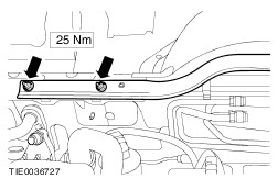
Remove the bulkhead extension panel. - Remove the retaining bolts.
- Detach the panel from the retaining clips.
| Left-hand drive vehicles | | -
Remove the battery tray.
For additional information, refer to: Battery Tray - 1.6L Duratec-16V (Sigma)/1.8L Duratec-HE (MI4)/2.0L Duratec-HE (MI4) (414-01 Battery, Mounting and Cables, Removal and Installation) /
Battery Tray - 1.6L Duratorq-TDCi (DV) Diesel/2.0L Duratorq-TDCi (DW) Diesel (414-01 Battery, Mounting and Cables, Removal and Installation).
| | | -
Detach the strut and spring assembly top mount brace from the bulkhead. | | | -
Remove the strut and spring assembly top mount brace. | All vehicles | | -
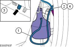
Remove the brake fluid reservoir extension. - Disconnect the feed hose coupling from the master cylinder.
| 10. Remove the components in the order indicated in the following illustration(s) and table(s). 2 - Low brake fluid warning indicator switch electrical connector 3 - Brake fluid main reservoir retaining pin 11. To install, reverse the removal procedure. | | -
Bleed the brake system.
For additional information, refer to: Brake System Bleeding (206-00 Brake System - General Information, General Procedures) /
Brake System Pressure Bleeding (206-00 Brake System - General Information, General Procedures).
| Removal Details Item 1 : Clutch master cylinder supply line | | -
CAUTION:Cap the clutch master cylinder supply line to prevent fluid loss or dirt ingress. Disconnect the clutch master cylinder supply line from the brake fluid main reservoir. | Item 4 : Brake fluid main reservoir CAUTION:Cap the brake fluid reservoir hose connections to prevent fluid loss or dirt ingress. |