| Removal and Installation Special Tool(s) | | Wrench, Fuel Tank Sender Unit (310-069) 23-055 | General Equipment WARNING:Do not smoke or carry lighted tobacco or open flame of any type when working on or near any fuel related components. Highly flammable vapors are always present and may ignite. Failure to follow these instructions may result in personal injury. WARNING:This procedure involves fuel handling. Be prepared for fuel spillage at all times and always observe fuel handling precautions. Failure to follow these instructions may result in personal injury. WARNING:The fuel system remains pressurized for a long time after the ignition is switched off. The fuel pressure must be released before attempting any repairs. Failure to follow these instructions may result in personal injury. | | -
Release the fuel system pressure.
For additional information, refer to: Fuel System Pressure Release (310-00 Fuel System - General Information, General Procedures).
| | | -
Drain the fuel tank.
For additional information, refer to: Fuel Tank Draining (310-00 Fuel System - General Information, General Procedures).
| | | -
Raise and support the vehicle.
For additional information, refer to: Lifting (100-02 Jacking and Lifting, Description and Operation).
| | | -
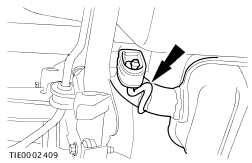
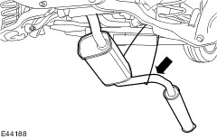
Detach the exhaust system from the middle hanger insulator. | | | -
Remove the exhaust flange nuts. - Discard the gasket and exhaust flange retaining nuts.
| | | -
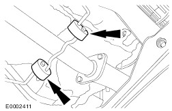
NOTE:With the aid of another technician support the exhaust. Detach the exhaust system from the front hanger insulators. | | | -
NOTE:With the aid of another technician support the exhaust. Position the exhaust to one side and secure to the body with tie-straps. | | | -
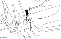
Remove the left hand side rear air deflector shield. | 9. Remove the components in the order indicated in the following illustration(s) and table(s). 1 - Exhaust pipe center heat shield retaining bolts 10 - Evaporative emission canister to fuel tank vent pipe quick release coupling See Removal Detail 10. To install, reverse the removal procedure. | | -
Initialize the door window motors.
For additional information, refer to: Door Window Motor Initialization (501-11 Glass, Frames and Mechanisms, General Procedures).
| Removal Details Item 3 : Fuel tank filler hose retaining clamps | | -
NOTE:Make a note of the position of the fuel tank filler hose retaining clamp. Make sure that the new replacement screw type clamp is positioned so that the screw head is in the same position as as the original filler hose retaining clamp. Remove and discard the fuel tank filler hose retaining clamp. | | | -
NOTE:Make a note of the position of the fuel tank filler hose retaining clamp. Make sure that the new replacement screw type clamp is positioned so that the screw head is in the same position as as the original filler hose retaining clamp. Remove and discard the fuel tank filler hose retaining clamp (rear sub-frame shown removed for clarity). | Item 4 : Fuel tank filler hose | | -
CAUTION:When removing the fuel tank filler hose, do not use any sharp edge tools to lever off the pipes. Failure to follow this instruction may result in damage to the filler hose. Remove the fuel tank filler hose. | Item 5 : Fuel tank vent hose retaining clamp | | -
NOTE:Make a note of the position of the fuel tank vent hose retaining clamp. Make sure that the new replacement screw type clamp is positioned so that the screw head is in the same position as as the original vent hose retaining clamp. Remove and discard the fuel tank vent hose retaining clamp (rear sub-frame shown removed for clarity). | Item 6 : Fuel tank vent hose | | -
CAUTION:When removing the fuel tank vent hose, do not use any sharp edge tools to lever off the pipes. Failure to follow this instruction may result in damage to the vent hose. Disconnect the fuel tank vent hose from the fuel tank filler pipe. | Item 7 : Evaporative emission canister vent pipe quick release coupling | | -
Disconnect the evaporative emission canister vent pipe quick release coupling from the evaporative emission canister. - Release the locking tangs
| Item 8 : Fuel line to fuel tank vent pipe quick release coupling | | -
Disconnect the fuel line to fuel tank vent pipe quick release coupling.
For additional information, refer to: Quick Release Coupling (310-00 Fuel System - General Information, General Procedures).
| Item 9 : Fuel tank fuel supply line quick release coupling | | -
Disconnect the fuel tank fuel supply line quick release coupling.
For additional information, refer to: Quick Release Coupling (310-00 Fuel System - General Information, General Procedures).
| Item 10 : Evaporative emission canister to fuel tank vent pipe quick release coupling | | -
Disconnect the evaporative emission canister to fuel tank vent pipe quick release coupling from the fuel tank. - Release the locking tangs
| Item 11 : Fuel tank support straps CAUTION:When supporting the fuel tank, use a suitable packing material to prevent damage to the underside of the fuel tank. | | -
Place a suitable transmission jack under the fuel tank. | Item 12 : Fuel tank CAUTION:When lowering the fuel tank, do not place excessive strain on the fuel lines and wiring harness. | | -
Partially lower the fuel tank. | Item 13 : Fuel pump module electrical connector | | -
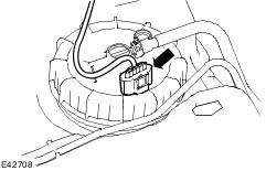
Disconnect the fuel pump module electrical connector. | Item 14 : Fuel tank vent hose retaining clamp | | -
NOTE:Make a note of the position of the fuel tank vent hose retaining clamp. Make sure that the new replacement screw type clamp is positioned so that the screw head is in the same position as as the original vent hose retaining clamp. Remove and discard the fuel tank vent hose retaining clamp. | Item 15 : Fuel tank vent hose | | -
CAUTION:When removing the fuel tank vent hose, do not use any sharp edge tools to lever off the pipes. Failure to follow this instruction may result in damage to the vent hose. Remove the fuel tank vent hose from the fuel tank. | Item 17 : Fuel supply line | | -
Disconnect the fuel supply line quick release coupling.
For additional information, refer to: Quick Release Coupling (310-00 Fuel System - General Information, General Procedures).
| Item 18 : Fuel pump module locking ring | | -
Using the special tool, remove the fuel pump locking ring. | Item 19 : Fuel pump module CAUTION:Make sure the fuel tank level sensor float and arm are not damaged during the removal of the fuel pump module. Installation Details Item 19 : Fuel pump module | | -
CAUTION:Make sure the fuel tank level sensor float and arm are not damaged during the installation of the fuel pump module. Make sure the arrows on the fuel tank and fuel pump module are aligned correctly. | Item 18 : Fuel pump module locking ring | | -
Using the special tool, install the fuel pump locking ring. | Item 14 : Fuel tank vent hose retaining clamp | | -
Install a new fuel tank vent hose retaining clamp in the position shown. | Item 12 : Fuel tank CAUTION:When installing the fuel tank, make sure the fuel lines do not get kinked or trapped. | | -
Partially raise the fuel tank. | Item 13 : Fuel pump module electrical connector | | -
Connect the fuel pump module electrical connector. | Item 11 : Fuel tank support straps | | -
Install the fuel tank support strap retaining bolts and remove the transmission jack. | Item 5 : Fuel tank vent hose retaining clamp | | -
Install a new fuel tank filler hose retaining clamp in the position shown (rear sub-frame shown removed for clarity). | Item 3 : Fuel tank filler hose retaining clamps | | -
Install a new fuel tank filler hose retaining clamp in the position shown. | | | -
Install a new fuel tank filler hose retaining clamp in the position shown (rear sub-frame shown removed for clarity). | |