| Diagnosis and Testing Refer to Wiring Diagrams Section 501-11, for schematic and connector information. Inspection and Verification - Verify the customer concern.
- Visually inspect for obvious signs of mechanical or electrical damage.
Visual Inspection Chart | Mechanical | Electrical | - Window seal
- Door window frame
| - Fuse(s)
- Electrical connector(s)
- Switch(es)
- Grid wire(s)
- Circuit(s)
| - If an obvious cause for an observed or reported concern is found, correct the cause (if possible) before proceeding to the next step.
- If the cause is not visually evident, verify the symptom and refer to the Symptom Chart.
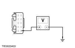
Symptom Chart Symptom Chart | Symptom | Possible Sources | Action | | All power windows are inoperative - front power windows | * Circuit(s). | * | | The left or right power window is inoperative - driver side | * Driver power window control switch. | * CARRY OUT the Driver Power Window Control Switch Component Test. REFER to the Wiring Diagrams. | | * Driver power window motor. * Circuit(s). | * | | The left or right power window is inoperative - passenger side | * Passenger power window control switch. | * CARRY OUT the Passenger Power Window Control Switch Component Test. REFER to the Wiring Diagrams. | | * Driver power window control switch. | * CARRY OUT the Driver Power Window Control Switch Component Test. REFER to the Wiring Diagrams. | | * Passenger power window motor. * Circuit(s). | * | | The one-touch down feature is inoperative - front power windows | * Driver power window control switch. | * CARRY OUT the Driver Power Window Control Switch Component Test. REFER to the Wiring Diagrams. | | The defrost system is inoperative | * Passenger Junction Box (PJB). | * For additional information, REFER to WDS. | | * Heated windshield relay. | * For additional information, REFER to WDS. | | * Heated windshield control switch. | * CARRY OUT the Heated Windshield Control Switch Component Test. REFER to the Wiring Diagrams. | | * Heated rear window relay. | * For additional information, REFER to WDS. | | * Heated rear window control switch. | * CARRY OUT the Heated Rear Window Control Switch Component Test. REFER to the Wiring Diagrams. | | * Heated rear window grid wire. * Circuit(s). | * For additional information, REFER to WDS. | | The defrost system will not shut off automatically | * Passenger Junction Box (PJB). * Heated windshield relay. * Heated rear window relay. | * For additional information, REFER to WDS. | Pinpoint Tests NOTE:Use a digital multimeter for all electrical measurements. | PINPOINT TEST A : ALL POWER WINDOWS ARE INOPERATIVE - FRONT POWER WINDOWS | | TEST CONDITIONS | DETAILS/RESULTS/ACTIONS | | A1: CHECK FOR VOLTAGE TO THE POWER WINDOW CONTROL SWITCHES | | | 1 Ignition switch in position II. | | | Do the power window control switch LEDs illuminate? Yes VERIFY the customer concern. No | | A2: CHECK FOR CONTINUITY BETWEEN THE DRIVER POWER WINDOW CONTROL SWITCH AND GROUND | | | 1 Ignition switch in position 0. | | | 2 Disconnect Driver Power Window Control Switch C488. | | | 3 Measure the resistance between the driver power window control switch C488 pin 1, circuit 31-AJ7 (BK), harness side and ground. | | | Is the resistance less than 5 ohms? Yes No REPAIR circuit 31-AJ7 (BK). TEST the system for normal operation. | | A3: CHECK THE VOLTAGE TO THE DRIVER POWER WINDOW CONTROL SWITCH | | | 1 Ignition switch in position II. | | | 2 Measure the voltage between the driver power window control switch C488 pin 10, circuit 15-AJ7 (GN/BU), harness side and ground. | | | Is the voltage greater than 10 volts? Yes VERIFY the customer concern. No REPAIR circuit 15-AJ7 (GN/BU). TEST the system for normal operation | | PINPOINT TEST B : THE LEFT OR RIGHT POWER WINDOW IS INOPERATIVE - DRIVER SIDE | | TEST CONDITIONS | DETAILS/RESULTS/ACTIONS | | B1: CHECK FOR IGNITION VOLTAGE TO THE DRIVER POWER WINDOW CONTROL SWITCH | | | 1 Ignition switch in position II. | | | Does the driver power window control switch LED illuminate? Yes No | | B2: CHECK FOR CONTINUITY BETWEEN THE DRIVER POWER WINDOW MOTOR AND GROUND | | | 1 Ignition switch in position 0. | | | 2 Disconnect Driver Power Window Motor C782 or C783. | | | 3 Measure the resistance between the: - left-hand drive vehicles - driver power window motor C782 pin 1, circuit 33-AJ26 (YE), harness side and ground (left-hand drive vehicle shown); or
- right-hand drive vehicles - driver power window motor C783 pin 2, circuit 33-AJ26A (YE), harness side and ground.
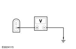
| | | Is the resistance less than 5 ohms? Yes No REPAIR circuit 33-AJ26 (YE) or circuit 33-AJ26A (YE). TEST the system for normal operation. | | B3: CHECK FOR VOLTAGE TO THE DRIVER POWER WINDOW MOTOR | | | 1 Ignition switch in position II. | | | 2 Operate the driver power window control switch to the DOWN position. | | | 3 Measure the voltage between the: - left-hand drive vehicles - driver power window motor C782 pin 2, circuit 32-AJ26 (WH), harness side and ground (left-hand drive vehicle shown); or
- right-hand drive vehicles - driver power window motor C782 pin 1, circuit 32-AJ26A (WH), harness side and ground.
| | | Is the voltage greater than 10 volts? Yes No REPAIR circuit 32-AJ26 (WH) or circuit 32-AJ26A (WH). TEST the system for normal operation. | | B4: CHECK THE DRIVER POWER WINDOW SWITCH FOR CONTINUITY TO GROUND | | | 1 Ignition switch in position 0. | | | 2 Disconnect Driver Power Window Control Switch C488. | | | 3 Measure the resistance between the driver power window control switch C488 pin 1, circuit 31-AJ7 (BK), harness side and ground. | | | Is the resistance less than 5 ohms? Yes No REPAIR circuit 31-AJ7 (BK). TEST the system for normal operation. | | B5: CHECK FOR VOLTAGE TO THE DRIVER POWER CONTROL SWITCH | | | 1 Ignition switch in position II. | | | 2 Measure the voltage between the driver power window control switch C488 pin 10, circuit 15-AJ7 (GN/BU), harness side and ground. | | | Is the voltage greater than 10 volts? Yes VERIFY the customer concern. No REPAIR circuit 15-AJ7 (GN/BU). TEST the system for normal operation. | | PINPOINT TEST C : THE LEFT OR RIGHT POWER WINDOW IS INOPERATIVE - PASSENGER SIDE | | TEST CONDITIONS | DETAILS/RESULTS/ACTIONS | | C1: CHECK FOR VOLTAGE TO THE PASSENGER POWER WINDOW CONTROL SWITCH | | | 1 Ignition switch in position II. | | | Does the passenger power window control switch LED illuminate? Yes No | | C2: CHECK THE PASSENGER POWER WINDOW CONTROL SWITCH GROUND CIRCUITS | | | 1 Ignition switch in position 0. | | | 2 Disconnect Passenger Power Window Control Switch C489. | | | 3 Measure the resistance between the passenger power window control switch C489 pin 3, circuit 32-AJ18 (WH/VT), harness side and ground; and between the passenger power window control switch C489 pin 6, circuit 33-AJ18 (YE/VT), harness side and ground. | | | Are the resistances less than 5 ohms? Yes No Repair circuit 32-AJ18 (WH/VT) or circuit 33-AJ18 (YE/VT). TEST the system for normal operation. | | C3: CHECK FOR CONTINUITY BETWEEN THE PASSENGER POWER WINDOW CONTROL SWITCH AND THE MOTOR | | | 1 Disconnect Passenger Power Window Motor C782 or C783. | | | 2 Measure the resistance between the: - left-hand drive vehicles - passenger power window control switch C489 pin 1, circuit 33-AJ17 (YE/VT), harness side and the passenger power window motor C783 pin 2, circuit 33-AJ17 (YE/VT), harness side (left-hand drive vehicle shown); or
- right-hand drive vehicles - passenger power window control switch C489 pin 1, circuit 33-AJ17A (YE/VT), harness side and the passenger power window motor C782 pin 1, circuit 33-AJ17A (YE/VT), harness side.
| | | Is the resistance less than 5 ohms? Yes No REPAIR circuit 33-AJ17 (YE/VT) or circuit 33-AJ17A (YE/VT). TEST the system for normal operation. | | C4: CHECK FOR CONTINUITY BETWEEN THE PASSENGER POWER WINDOW CONTROL SWITCH AND THE MOTOR | | | 1 Measure the resistance between the: - left-hand drive vehicles - passenger power window control switch C489 pin 7, circuit 32-AJ17 (WH/VT), harness side and the passenger power window motor C783 pin 1, circuit 32-AJ17 (WH/VT), harness side (left-hand drive vehicle shown); or
- right-hand drive vehicles - passenger power window control switch C489 pin 7, circuit 32-AJ17A (WH/VT), harness side and the passenger power window motor C783 pin 2, circuit 32-AJ17A (WH/VT), harness side.
| | | Is the resistance less than 5 ohms? Yes No REPAIR circuit 32-AJ17 (WH/VT) or circuit 33-AJ17A (YE/VT). TEST the system for normal operation. | | C5: CHECK THE PASSENGER POWER WINDOW CONTROL SWITCH GROUND CIRCUIT | | | 1 Ignition switch in position 0. | | | 2 Disconnect Passenger Power Window Control Switch C489. | | | 3 Measure the resistance between the passenger power window control switch C489 pin 4, circuit 31-LH31 (BK), harness side and ground. | | | Is the resistance less than 5 ohms? Yes No REPAIR circuit 31-LH31 (BK). TEST the system for normal operation. | | C6: CHECK FOR VOLTAGE TO THE PASSENGER POWER WINDOW CONTROL SWITCH | | | 1 Ignition switch in position II. | | | 2 Measure the voltage between the passenger power window control switch C489 pin 2, circuit 15-AJ18 (GN/WH), harness side and ground. | | | Is the voltage greater than 10 volts? Yes VERIFY the customer concern. No REPAIR circuit 15-AJ18 (GN/WH). TEST the system for normal operation. | |