| Removal and Installation Special Tool(s) | | Pliers, Door Trim Removal 501-028A (43-001A) | General Equipment Materials Name Specification Adhesive - Loctite 243
WSK-M2G349-A7 Vehicles built up to 10/2005 | | -
Remove the passenger air bag module.
For additional information, refer to: Passenger Air Bag Module - Vehicles Built Up To: 10/2005 (501-20B Supplemental Restraint System, Removal and Installation).
| All vehicles | | -
Remove the floor console extension.
For additional information, refer to: Floor Console Extension (501-12 Instrument Panel and Console, Removal and Installation).
| Vehicles built 03/2007 onwards NOTE:This step is only necessary if the vehicle is euipped with a center armrest. | | -
Remove the floor console side trim (on both sides). | | | -
Remove the floor console. | | | -
Remove the gearshift lever bracket. | Vehicles built 10/2005 onwards WARNING:The supplemental restraint system (SRS) is active for a certain length of time after the power supply has been disconnected. Wait for a minimum of 3 minutes before disconnecting or removing any SRS components. WARNING:Wear safety goggles. WARNING:Do not use radio key code savers when working on the supplemental restraint system. WARNING:Always carry a live air bag module with the bag and trim cover pointed away from the body. WARNING:Live air bag modules must only be placed on work benches which have been ground bonded and with the trim cover facing up. WARNING:Never probe the electrical connectors of air bag modules or any other supplemental restraint system component. | | -
Disconnect the battery ground cable.
For additional information, refer to: Battery Disconnect and Connect (414-01 Battery, Mounting and Cables, General Procedures).
| | | -
Detach the glove compartment from the instrument panel. - Remove the instrument panel lower panel.
- Remove the instrument panel outer trim panel.
| | | -
Remove the glove compartment. - Disconnect the passenger air bag deactivation (PAD) switch electrical connector (if equipped).
- Disconnect the MP3 auxiliary connector electrical connector (if equipped).
- Disconnect the glove compartment lamp switch electrical connector.
| | | -
Remove the passenger air bag module support bracket. | | | -
Disconnect the passenger air bag module electrical connector. | All vehicles WARNING:When removing or installing the instrument panel, care must be taken not to scratch or damage the instrument panel surface. | | -
Remove the A-pillar trim panels.
For additional information, refer to: A-Pillar Trim Panel (501-05 Interior Trim and Ornamentation, Removal and Installation).
| | | -
Remove the climate control assembly. For additional information, refer to: (412-04 Control Components) Climate Control Assembly - Vehicles With: Manual Temperature Control (Removal and Installation), Climate Control Assembly - Vehicles With: Automatic Temperature Control (Removal and Installation), Climate Control Assembly - Vehicles With: Digital Versatile Disc (DVD) Navigation System (Removal and Installation). | | | -
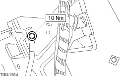
Release the steering column locking lever and lower the steering column. | 14. Remove the components in the order indicated in the following illustration(s) and table(s). 5 - Instrument panel upper outer trim panels 6 - Instrument panel upper inner trim panel 7 - Instrument panel lower outer trim panel 8 - Instrument panel lower panel 9 - Steering column upper shroud 14 - In-vehicle temperature sensor electrical connector (if equipped) 15 - In-vehicle temperature sensor (if equipped) 19 - Steering column bracket retaining screws 23 - In-vehicle crossbeam inner retaining bolts 15. To install, reverse the removal procedure. Removal Details Item 2 : Door hinge center retaining bolts | | -
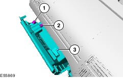
CAUTION:Protect the door using a soft cloth to prevent damage. NOTE:Remove both front doors. With the aid of another technician and a suitable trolley jack, support the door. | Item 3 : Door (left-hand door shown) | | -
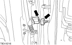
Detach the electrical connector from the A-pillar (on both sides). | | | -
Remove the front door (on both sides). - Disconnect the electrical connector.
| Item 4 : In-vehicle crossbeam outer retaining bolts | | -
CAUTION:Do not fully remove the in-vehicle crossbeam outer retaining bolts. Loosen the in-vehicle crossbeam outer retaining bolts by two complete turns on both sides. | Item 10 : Instrument cluster | | -
Remove the instrument cluster retaining screws. | | | -
CAUTION:Make sure the instrument cluster lens is protected by a clean cloth. Failure to follow this instruction may result in damage to the instrument cluster. Using the special tool, detach the instrument cluster from the instrument panel. | | | -
CAUTION: Make sure the instrument cluster lens is protected by a clean soft cloth. Failure to follow this instruction may result in damage to the instrument cluster lens. Disconnect the electrical connector and remove the instrument cluster. - Press the locking tang.
- Detach the self locating electrical connector.
| Item 11 : Headlamp switch | | -
Remove the headlamp switch. - Disconnect the electrical connector.
- Release the retaining clips.
| Item 12 : Outer register | | -
Remove the outer register on both sides (left-hand side shown). - Release the retaining clips.
| Item 13 : Stowage compartment lid | | -
Open the stowage compartment lid to gain access to the instrument panel retaining screws. | Item 17 : Gearshift lever mounting bracket | | -
Disconnect the ground cable from the gearshift lever mounting bracket. | | | -
Detach the wiring harness from the gearshift lever mounting bracket. | | | -
Detach the gearshift lever from the gearshift lever mounting bracket and position to one side. | | | -
Remove the gearshift lever mounting bracket. - Remove the retaining bolts on both sides (left-hand side shown).
| Item 22 : Central junction box | | -
Detach the central junction box from the in-vehicle crossbeam. | Item 24 : Instrument panel | | -
Remove the instrument panel. - Move the top of the instrument panel rearwards to gain access to three retaining screws.
- Remove the retaining screws.
| | | -
NOTE:This step is only necessary when installing a new component. Remove the passenger air bag module (if equipped). | Installation Details Item 18 : Steering column shaft to steering gear pinion retaining bolt WARNING:Install a new steering column shaft to steering gear pinion retaining bolt. Failure to follow this instruction may result in personal injury. Item 2 : Door hinge center retaining bolts | | -
Apply a coating of adhesive to the door hinge center retaining bolts. | |