The Focus C-MAX 2003.75 (06/2003) has a completely new protected passenger compartment.
Deformation stages on the vehicle front-end
1
-
Bolted sheet metal crash element
Different components/modules will be damaged on this vehicle depending on the severity of the impact.
In minor impacts often only the bolted sheet metal crash element will be damaged. Thanks to the bolt connections that attach it to the side member, the crash element can be renewed very easily.
More severe impacts that cannot be absorbed by the sheet metal crash element alone, will then affect the front areas of the two side members, which will also absorb some of the energy.
Very severe impacts are absorbed by the entire front end structure (side members) as far as the bulkhead and floor pan.
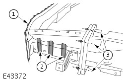
Sheet metal crash element
The sheet metal crash element is made from high-strength sheet steel. As a result, it has been possible to reduce the cross section of the existing box section.
1
-
Structured reinforcing panel
2
-
Designated yield points
3
-
Bolted joint joining the sheet metal crash element to the front side member
To increase the rigidity of the front crossmember still further, the crossmember was fitted with an additional, structured reinforcing panel (1).
The designated yield points (2) absorb the impact energy that arises with minor impacts.
A damaged sheet-metal crash element can be very easily renewed thanks to the bolted joints (3).
NOTE:Deformed crash elements must not be straightened or repaired.
Rear end design features
The rear sheet metal crossmember joins together the two ends of the side members, thereby helping to increase the passive safety in the event of a rear impact.
1
-
Sheet metal crossmember
2
-
Designated yield points on the crash element
The slightly curved basic shape of the bolted-on crossmember is able to convert crash energy into deformation energy more easily.
In lesser impacts this prevents deformation of the side members and therefore of the body structure.
The impact energy is absorbed by the designated yield points.
Laser weld seams on the side members
Laser weld seams have been used in production for some time to join materials of different thicknesses in the load-bearing areas of the body.
If these areas are damaged, special repair procedures must be followed. The respective applicable repair methods can be found in the corresponding documentation such as the Technicians Information "Repairing Accident Damage" and the Body Repair Manuals.
Cut locations right on the laser weld seams are not advisable, as currently there are no joining techniques suitable for use in repair procedures that would re-create joins of the same quality.
At the vehicle front end, the laser weld seams are located inside the crash zones that are directly affected.
Position of the laser weld seams on the front end
MIG brazed areas
1
-
Outer wheelhouse / door sill reinforcement (inner)
2
-
A-pillar reinforcement / A-pillar inner panel (inner)
3
-
Bulkhead reinforcement / A-pillar (outer)
These MIG brazed joints must be replaced by MIG welds at another place if a repair is performed.
- These MIG welds must not be carried out on or near existing MIG brazed seams as even the smallest amount of brazing solder can result in a reduction in the strength of the weld seam.
- When performing these repairs, the corresponding requirements in subsections 501-27, 501-29 and 501-30 must be observed.
High-strength steel panels
High strength steel panels are used even more on the Focus C-MAX.
NOTE:The instructions for working on high strength steel panels given in subsection 501-25 must be followed during body repair work.
Components overview, the high-strength steel panels are indicated with arrows.
Corrosion prevention measures
On the Focus C-MAX, all external and corrosion prone steel body panels are zinc plated on both sides.
The roof and some internal reinforcement panels on the floor pan and on the A-, B- and C-pillars are not zinc plated.
NOTE:The instructions for working on zinc plated steel panels given in subsection 501-25 must be followed during body repair work.
Further corrosion protection measures
Clinched flange sealer is applied to the bonnet, boot lid and the doors after zinc plating has been done.
When applying clinched flange sealer as part of body repair work, an overlap of at least 2 mm must be taken into account as well as the minimum height and width. The overlap area covers the area from where the sealer starts to where it finishes.
NOTE:When body repairs are performed or if these components are renewed, this procedure must be observed.
Further corrosion protection measures are performed on the bodywork.
NOTE:The original corrosion protection must be re-created after working on the bodywork.