| Removal and Installation | | -
Replacement Parts - Fender panel reinforcement
| Removal NOTE: Where possible, a partial replacement of the fender panel reinforcement is preferred to a complete replacement, as this can save a considerable amount of time on assembly work in the inner area of the A-pillar. The partial replacement options shown do not require the MIG brazed joints on the A-pillar to be detached. | | -
General notes - Necessary removal work: Bonnet, wing, bumper, door, front module, headlamp and wheelhouse liner.
| | | -
Fender panel reinforcement - Cut locations for partial replacement.
| | | -
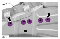
Fender panel reinforcement - Mill out the spot welds.
- Grind out the MIG brazed joints.
| | | -
Fender panel reinforcement - Mill out the hidden spot welds.
| Installation NOTE: Before resistance spot welding of body panels with a total panel thickness of 3 mm and greater, the welding equipment instructions contained in sub-section 501-25A must be followed. | | -
Prepare fender panel reinforcement - Cut off the sheet metal tabs, leaving a residual flange of approx. 5 mm.
- Drill holes for puddle welding.
| | | -
- When carrying out a repair, the MIG brazed joints made during vehicle production must be replaced by MIG weld joints in a different location (see diagram E52178).
- These MIG welds must not be carried out on or near existing MIG brazed seams as even the smallest amount of brazing solder can result in a reduction in the strength of the weld seam.
Offer up the fender panel reinforcement and secure it. - Mark up the welding zones on the A-pillar along the contour of the fender panel reinforcement.
| | | -
- During installation the new fender panel reinforcement will be welded to the A-pillar cover panel and the A-pillar reinforcement.
- The areas on the A-pillar cover panel are ground through completely to give access to the A-pillar reinforcement underneath.
Prepare the A-pillar - Grind the welding zones on the A-pillar as required.
| | | -
Fender panel reinforcement - Continuous MIG seam weld.
| | | -
Fender panel reinforcement | | | -
- Puddle weld through the hole openings of the fender panel reinforcement.
- After carrying out the repair carefully apply cavity seal. Also treat the areas of the original MIG brazed joints.
Fender panel reinforcement | | |