
Contour V6-153 2.5L DOHC (1996)
INSTALLATION
CAUTION: If upper front engine support insulator or front engine support bracket has been removed, engine and transaxle position must be
realigned to front subframe. Failure to realign engine and transaxle may result in possible component damage.
1. Raise and support vehicle, then remove two front subframe through bolt bolts and lefthand front engine support insulator.
Fig. 2 Powertrain alignment gauge tool installation
2. Install powertrain alignment gauge T94P-6000-AH, or equivalent, to transaxle bracket and front subframe. Torque vertical bolts and through bolt
to 20 ft lb.
3. Loosen righthand front engine support insulator through bolt, then lower vehicle.
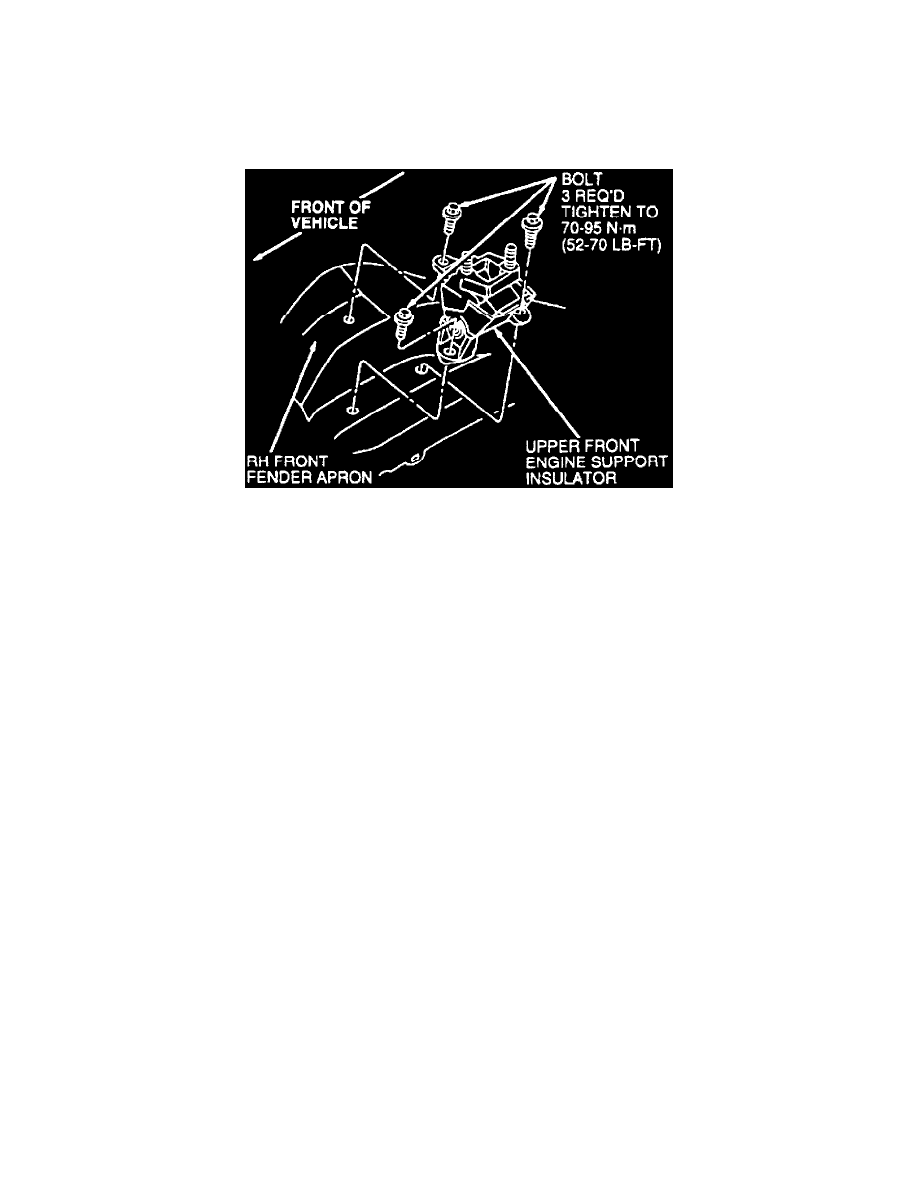
4. Position power steering hose bracket and return hose onto upper front support insulator, then install upper front engine support insulator and bolts
to righthand front fender apron.
5. Position radiator coolant recovery reservoir. Tighten bolts to 6-9 ft lb.
6. Install upper front engine support bracket onto engine and upper front engine support insulator. Torque new self-locking upper front engine
support bracket nuts to 7 ft lb. Engine support nuts are self-locking and must be replaced with new self-locking nuts when serviced.
7. Remove engine support tool, then torque upper front engine support bracket nuts to 52-70 ft lb.
8. Raise and support vehicle, then observe position of righthand front engine support insulator. Insulator must be centered in transaxle bracket and in
perfect front-to-rear alignment.
9. Tighten righthand front engine support insulator through bolt.
10. Remove three gauge tool bolts and gauge tool.
11. Install lefthand front engine support insulator to front subframe with two bolts, then torque bolts to 7 ft lb. Observe insulator to ensure perfect
front-to-rear alignment, then torque bolts to 30-40 ft lb.
12. Install lefthand front engine support insulator through bolt.
13. Install power steering pressure hose to pump, then position pressure hose bracket to upper front engine support bracket and install bolt.
14. Connect engine control sensor wiring to power steering pressure switch connector.
15. Position ignition wires and retainer onto upper front engine support bracket mounting studs.
16. Install water pump pulley shield and screws.
17. Fill power steering system reservoir
18. Run engine and check for leaks.