
Crown Victoria V8-4.6L Flex Fuel (2008)
Driver/Vehicle Information Display: Initial Inspection and Diagnostic Overview
Inspection and Verification
INSPECTION AND VERIFICATION
WARNING: If equipped with fire suppression system, refer to Fire Suppression System for Important Safety Warnings. Failure to follow this
instruction may result in serious personal injury.
1. Verify the customer concern.
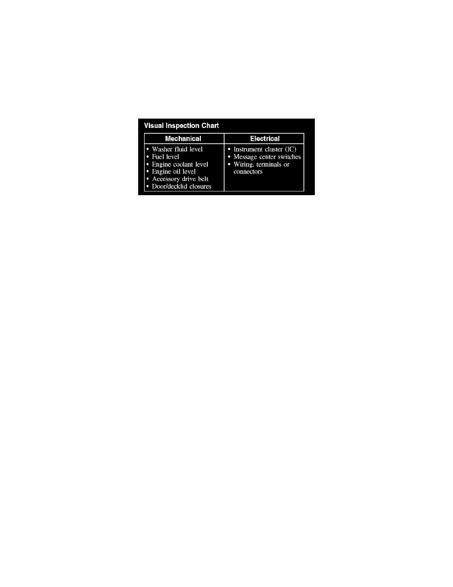
2. Visually inspect for obvious signs of mechanical or electrical damage.
Visual Inspection Chart
3. If an obvious cause for an observed or reported concern is found, correct the cause (if possible) before proceeding to the next step.
4. NOTE: Make sure to use the latest scan tool software release.
If the cause is not visually evident, connect the scan tool to the data link connector (DLC).
5. NOTE: The vehicle communication module (VCM) LED prove-out confirms power and ground from the DLC are provided to the VCM.
If the scan tool does not communicate with the VCM:
-
Check the VCM connection to the vehicle.
-
Check the scan tool connection to the VCM.
-
Refer to Information Bus (Module Communications Network), No Power To The Scan Tool, to diagnose no communication with the scan tool.
6. If the scan tool does not communicate with the vehicle:
-
Verify the ignition key is in the ON position.
-
Verify the scan tool operation with a known good vehicle.
-
Refer to Information Bus (Module Communications Network) to diagnose no response from the PCM.
7. Carry out the network test:
-
If the scan tool responds with no communication for one or more modules, refer to Information Bus (Module Communications Network).
-
If the network test passes, retrieve and record the continuous memory DTCs.
8. Clear the continuous DTCs and carry out the self-test diagnostics for the instrument cluster (IC) and the lighting control module (LCM).
9. If the DTCs retrieved are related to the concern, go to DTC Charts. For all other DTCs, refer to Body Control Systems (Multifunction Electronic
Control Module). See: Instrument Panel, Gauges and Warning Indicators/Testing and Inspection/Diagnostic Trouble Code
Descriptions/Information and Message Center
10. If no DTCs related to the concern are retrieved, GO to Symptom Chart. See: Symptom Related Diagnostic Procedures
Principles of Operation
PRINCIPLES OF OPERATION
The message center electronic functions use hardwired inputs, the standard corporate protocol (SCP) network, and the controller area network (CAN) to
transmit and receive information. It is very important to understand:
-
where the input (command) originates.
-
all the information (messages) necessary in order for a feature to operate.
-
which module(s) receive(s) the input or command message.
-
if the module which received the input (message) controls the output of the feature, or if it outputs a message over the CAN circuit to another
module.
-
which module controls the output of the feature.
The message center provides the following features:
-
Information displays