
Crown Victoria V8-4.6L Flex Fuel (2008)
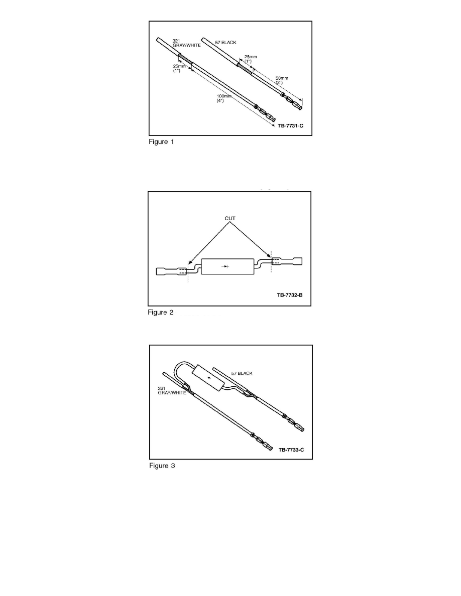
5. Strip 1" (25 mm) of insulation away from circuit 57 approximately 2" (50 mm) from the connector. (Figure 1)
6. Strip 1" (25 mm ) of insulation away from circuit 321 approximately 4" (100 mm) from the connector. (Figure 1)
7. Cut the butt connectors from the diode and strip approximately 1.25" (32 mm) of insulation from the cut ends of the wires. (Figure 2)
8. Twist the ends of the diode wires around the exposed wire on circuits 57 and 321. (Figure 3)
NOTE
THE DIODE MUST BE INSTALLED TO ALLOW CURRENT FLOW FROM CIRCUIT 57 TO CIRCUIT 321 (THE ARROW ON THE DIODE
MUST POINT FROM CIRCUIT 57 TO CIRCUIT 321). ORIENT THE DIODE WIRES AWAY FROM THE TERMINAL ENDS OF CIRCUITS
57 (BK) AND 321(GY/WH) AS SHOWN IN THE ILLUSTRATIONS. THIS WILL ALLOW HEAT SHRINK TUBING TO BE SLIPPED ON
THE WIRES.
9. Solder the diode wires to circuits 57 and 321. Use rosin core mildly activated (RMA) solder.
NOTE