
Crown Victoria V8-4.6L SOHC VIN 6 (1996)
Brake Pad: Service and Repair
REMOVAL
1. Remove brake fluid until reservoir is half full.
2. If equipped, turn air suspension service switch OFF.
3. Raise and support front of vehicle, then remove wheel and tire assembly.
4. Remove caliper locating pins.
5. Lift caliper assembly from adapter plate, then remove outer shoe from caliper assembly. If necessary, slip shoe down caliper leg until clip is
disengaged.
6. Remove inner shoe and lining assembly. If necessary, pull shoe straight out of piston. This should require a force as high as 20-30 lbs.
7. Suspend caliper from inner fender housing with wire to avoid damaging brake hose.
8. Remove and discard locating pin insulators and plastic sleeves.
INSTALLATION
1. Using a four-inch C-clamp and block of wood 2 3/4 x 1 inch and approximately 3/4 inch thick, seat caliper piston in bore, then remove C-clamp
and wooden block.
CAUTION: Some models have pistons made of phenolic material. Do not seat these pistons in bore by applying C-clamp directly to piston. Use
extra care during this procedure to prevent damage to the piston. Metal or sharp objects should not come into direct contact with the piston or
damage may result.
2. Install locating pin insulators and plastic sleeves on caliper housing. Ensure insulators and sleeves are properly positioned.
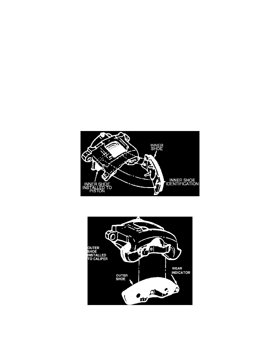
3. Install inner shoe and lining assembly on caliper piston. Some inner brake shoes are marked LH (lefthand) and RH (righthand) and must be
installed on the proper caliper. Use care to not bend spring clips too far during installation in piston, otherwise distortion and rattles may result.
Fig. 10 Outer Brake Shoe Installation On Caliper
4. Install outer brake shoe and lining assembly. Ensure shoes are installed on proper caliper and clip and buttons on shoe are properly seated. Outer
shoe can be identified as lefthand and righthand by wear indicator. Wear indicators must be installed toward front of vehicle.
5. Install locating pins.
6. Install wheel and tire assembly, then lower vehicle.
7. Turn air suspension service switch ON, if equipped.