
Crown Victoria V8-4.6L SOHC VIN 6 (1996)
Intake Manifold: Service and Repair
Removal
SPECIAL SERVICE TOOL(S) REQUIRED
Fuel Pressure Gauge T8OL-9974-B
REMOVAL
NOTE: When the battery has been disconnected or reconnected, volatile memory information will be lost. The affected systems will have to be
programmed by the technician or customer. These systems include: radio station presets, clock settings, seat memory, mirror memory, window
memory and customer input keyless entry codes.
1. Disconnect the battery ground cable.
2. Drain the cooling system.
3. Remove the engine cover (covering the throttle body).
4. Disconnect the crankcase ventilation tube and the idle air control valve inlet tube from the air cleaner outlet tube. Remove the air cleaner outlet
tube.
5. WARNING: The fuel supply lines on vehicles equipped with fuel injected engines remain pressurized for long periods after engine shut
down. The fuel system pressure must be relieved prior to fuel system service, to prevent possible injury.
Connect the Multiport Fuel Injection (MFI) Fuel Pressure Gauge (T8OL-9974-B) to the fuel pressure relief valve on the fuel supply manifold.
Open the manual valve on the gauge to relieve the fuel system pressure. Once the pressure is relieved, close the valve and remove the gauge.
6. Remove the locking clip from the pressure and return fuel line spring lock couplings. Using the spring lock coupling disconnect tools
(D87L-9280-A for 3/8-inch line, D87L-9280-B for 1/2-inch line) on the couplings. Push the tool into the cage opening to release the female fitting
from the garter spring. Remove the tool and pull the male coupling and fitting apart. Install protective caps over the lines and the fuel rail.
7. Disconnect the upper radiator hose from the water outlet connection and position it out of the way.
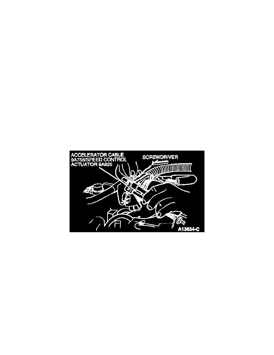
Accelerator Cable
8. Disconnect the accelerator cable and the speed control actuator cable from the throttle body and the locator. Remove the screws retaining the
cables to the accelerator cable bracket and position the cables out of the way.
9. Disconnect the wiring connectors from the throttle position sensor (TP), idle air control valve (IAC) and the engine coolant temperature sensor
(ECT). Disconnect the wiring connectors from the LH fuel injectors and the two wiring locators from the fuel rail. Position the harness out of the
way.
10. CAUTION: Do not pull directly on the ignition wires, the wires could separate from the connectors inside the boots.
Disconnect the ignition wires from the LH spark plugs and position them out of the way.
11. Remove the bolts retaining the spark plug wiring harness bracket to the intake manifold and the generator. Disconnect the ignition wires from the
locators and remove the bracket.
12. Remove the serpentine drive belt from the generator pulley.
13. Remove the generator retaining bolts and position it out of the way.
14. Remove the PCV valve and tube.
15. Disconnect the wiring connectors from the water temperature indicator sender unit and the EGR vacuum regulator solenoid. Disconnect the RH
fuel injector connectors and harness locators from the fuel rail. Position the harness out of the way.
16. CAUTION: Do not pull directly on the ignition wires, the wires could separate from the connectors inside the boots.