
Crown Victoria V8-4.6L SOHC VIN 6 (1996)
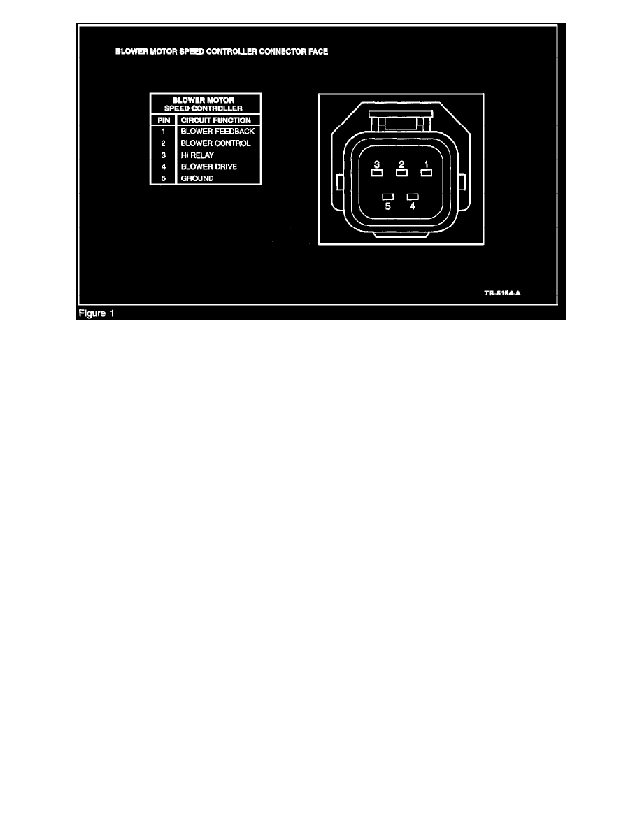
NOTE: REFER TO FIGURE 1 FOR CONNECTOR VIEW.
2. Refer to the appropriate pinpoint test in the Service/Workshop Manual, except for checking the EATC/DATC module. When checking the
EATC/DATC module, set the blower motor speed to HIGH blower and measure the voltage between the blower motor high blower relay circuit
(Pin 3 at the controller) and ground at the EATC/DATC module connector.
a.
If the voltage is within 2 volts of battery voltage, measure the resistance between the blower motor speed controller connector Pin 3 and the
corresponding circuit/pin at the EATC/DATC module connector. If the resistance is 5 ohms or less, install a new blower motor speed
controller (19E624). If the resistance is greater than 5 ohms, repair the circuit. Retest the system for proper operation.
b.
If the voltage is more than 2 volts below battery voltage, measure the resistance between the blower motor speed controller connector Pin 3
and ground. If the resistance is 5 ohms or less, repair the circuit. If the resistance is greater than 5 ohms, install a new EATC/DATC module
(19980). Retest the system for normal operation.
3. Set the blower speed control to HIGH and measure the voltage between the blower motor control high blower relay circuit (Pin 3 at the controller)
and ground at the EATC/DATC module connector.
a.
If the voltage is within 2 volts of battery voltage, measure the resistance between the blower motor speed controller connector Pin 3 and the
corresponding circuit/pin at the EATC/DATC module connector. If the resistance is 5 ohms or less, install a new blower motor speed
controller (19E624). If the resistance is greater than 5 ohms, repair the circuit. Retest the system for proper operation.
b.
If the voltage is more than 2 volts below battery voltage, measure the resistance between the blower motor speed controller connector Pin 3
and ground. If the resistance is greater than 5 ohms, install a new EATC/DATC module (19980). If the resistance is 5 ohms or less, repair
the circuit. Retest the system for normal operation.
4. Set the blower speed control to any speed other than HIGH and measure the voltage between the blower motor control blower control circuit (Pin
2 at the controller) and ground at the EATC/DATC module.
a.
If the voltage is below 1 volt, measure the resistance between the blower motor speed controller connector Pin 1 and ground. If the
resistance is greater than 5 ohms, install a new EATC/DATC module (19980). If the resistance is 5 ohms or less, repair the circuit. Retest
the system for normal operation.
b.
If the voltage is between 1 and 3 volts, measure the resistance of the circuit between the blower motor speed controller connector Pin 2 and
the corresponding pin at the EATC/DATC module connector. If the resistance is 5 ohms or less, install a new blower motor speed controller
(19E624). If the resistance is greater than 5 ohms, repair the circuit. Retest the system for normal operation.
c.
If the voltage is greater than 3 volts, measure the resistance of the circuit between the blower motor speed controller connector Pin 1 and the
corresponding pin at the EATC/DATC module connector. If the resistance is 5 ohms or less; install a new blower motor speed controller
(19E624). If. the resistance is greater than 5 ohms, repair the circuit. Retest the system for normal operation.