Crown Victoria V8-4.6L SOHC VIN 6 (1996)

Courtesy Lamp: Initial Inspection and Diagnostic Overview
Inspection and Verification (Start Testing Here)
Inspection and Verification - Illuminated Entry
1. Verify the customer's concern by operating the illuminated entry system to duplicate the condition.
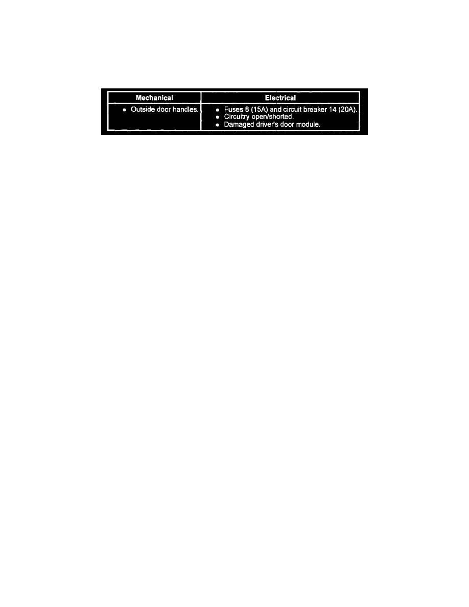
Visual Inspection Chart - Illuminated Entry
2. Inspect to determine if one of the mechanical or electrical concerns from the Visual Inspection chart apply.
3. If the inspection reveals obvious concerns that can be readily serviced, correct the concern before continuing with Inspection and Verification.
4. If the concern(s) remains after the inspection, use Rotunda New Generation (NGS) Tester 007-00500, connected to the data link connector (DLC)
to retneve continuous diagnostic trouble codes (DTCS) and to execute Self Test Diagnostics for the lighting control module and driver door
module.
5. If self test is passed and no diagnostic trouble codes (DTCs) are retrieved, go to Symptom Chart to continue diagnosis. See: Symptom Related
Diagnostic Procedures/Illuminated Entry
6. If diagnostic trouble codes (DTCs) are retrieved, go to Lighting Control Module (LCM) Diagnostic Trouble Codes (DTCs) Index. See:
Diagnostic Trouble Code Descriptions/Illuminated Entry/Lighting Control Module (LCM) DTC Index
7. If the lighting control module and driver door module can not be accessed by the NGS go to Pinpoint Test BA for lighting control module or go to
Pinpoint Test BB for Driver Door Module. See: Pinpoint Tests/Illuminated Entry/BB - No Communication With Driver Door Module (DDM)
With Scan Tool
New Generation Star (NGS) Tester Usage
The Service Bay Diagnostic System (SBDS), Rotunda Part Number 001-00001, may also be used to diagnose this system. Refer to the User's Manual
when using the SBDS to retrieve or clear DTCs.
NOTE: Ford DOES NOT provide a procedure to retrieve or clear DTCs other than with the method described below.
New Generation Star Tester Hookup and Vehicle Selection
NOTE: Before any diagnostics can be performed on the communication system, use Rotunda New Generation Star Tester 007-00500 or equivalent:
1. Turn ignition switch to OFF position.
2. Select the appropriate program card for the vehicle.
3. With the New Generation Star Tester control unit facing away from you, insert the program card into the slot on the back. If you insert the card
incorrectly, New Generation Star Tester will not work.
4. Plug the New Generation Star Tester data link connector (DLC) cable to the vehicle DLC port (OBDII Connector).
5. Turn ignition switch to RUN position.
6. Plug the power cable into the vehicle's cigar lighter or into the battery hookup adapter if using the alternative hookup. New Generation Star Tester
will perform an initialization, which checks that the New Generation Star Tester memory verifies the vehicle interface module matches the
program card software. If the screen displays an error message, refer to Appendix C New Generation Star Tester Operator Handbook, System
Messages.
7. Menu item "Vehicle and Engine Selection" is highlighted. Press trigger to select.
8. Rotate dial to menu item "Select New Vehicle Model and Year" - press trigger.
