Crown Victoria V8-4.6L SOHC VIN 6 (1996)

Information Bus: Testing and Inspection
Flow of Diagnosis
Inspection and Verification
1. Verify the customer's original concern.
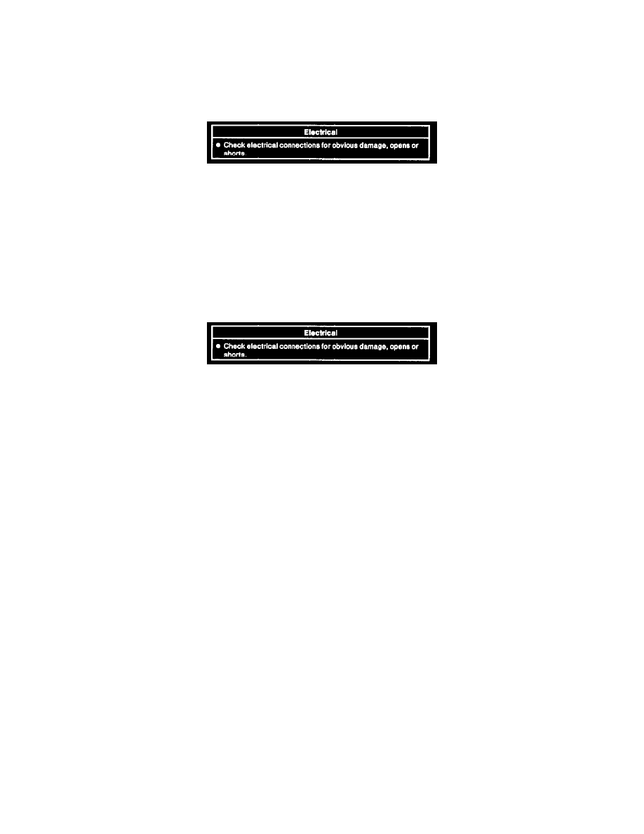
Visual Inspection Chart
2. Inspect to determine if one of the electrical concerns listed in the Visual Inspection Chart apply.
3. Inspect Pin 2, Pin 7 and Pin 10 on the data link connector (DLC) for loose, bent, deformed, corroded or broken pins. If pin is damaged, service or
replace pin, verify communication with Rotunda New Generation Star Tester 00 7-00500 or equivalent.
4. If the concern(s) remains after the inspection, continue with New Generation Star Tester Driven Diagnostics.
Initial Inspection and Diagnostic Overview
Inspection and Verification
1. Verify the customer's original concern.
Visual Inspection Chart
2. Inspect to determine if one of the electrical concerns listed in the Visual Inspection Chart apply.
3. Inspect Pin 2, Pin 7 and Pin 10 on the data link connector (DLC) for loose, bent, deformed, corroded or broken pins. If pin is damaged, service or
replace pin, verify communication with Rotunda New Generation Star Tester 00 7-00500 or equivalent.
4. If the concern(s) remains after the inspection, continue with New Generation Star Tester Driven Diagnostics.
Reading and Clearing Diagnostic Trouble Codes
1. Perform New Generation Star Te8ter Hookup and Vehicle Selection.
NOTE: The ignition switch must be in RUN position or test will fail.
2. Rotate dial to menu item Diagnostic Data Link and press trigger.
3. Select module to test by rotating dial to highlight module and press trigger.
4. Menu item Diagnostic Test Modes is highlighted. Press trigger.
5. Rotate dial to menu item Retrieve/Clear Continuous DTC, press trigger, then press start (Button 3).
6. Clear individual DTC from selected module, highlight DTC by rotating dial then press Button 8.
7. Clear all DTCs from selected module, press Button 7.
Communication System Diagnostic Notes
Before proceeding to the network index charts to diagnose a network DTC, review equipment level of vehicle. Make note of module and systems vehicle
is not equipped with. Before proceeding to a pinpoint test, make sure DTC being diagnosed is referencing a module or system which the vehicle is
equipped with. The New Generation Star (NGS) tester may produce a network DTC for no communication if the vehicle is not equipped with the suspect
module or system. The New Generation Star (NGS) tester will interpret a not equipped module as a communication failure. If a DTC is retrieved for a
not equipped module or system disregard this DTC. If a not equipped DTC is the only DTC retrieved the communication system self test should be
considered passed.
Diagnostic Commands
NOTE: This test is used to verify the operation of the output circuitry of the module being tested. The ignition switch must be in RUN position or test
will fail.
1. Perform New Generation Star Tester Hookup and Vehicle Selection.
2. Rotate dial to menu item Diagnostic Data Link and press trigger.
3. Select module by rotating dial to highlight module and press trigger.
4. Rotate dial to highlight menu item Active/Command Modes, press trigger.
