
Crown Victoria V8-4.6L SOHC VIN 6 (1996)
NOTE: Before any diagnostics can be performed on the communication system, use Rotunda New Generation Star Tester 007-00500 or equivalent.
1. Turn ignition switch to OFF position.
2. Select the appropriate program card for the vehicle.
3. With the New Generation Star Tester control unit facing away from you, insert the program card into the slot on the back. If you insert the card
incorrectly, New Generation Star Tester will not work.
4. Plug the New Generation Star Tester data link connector (DLC) cable to the vehicle DLC port (OBDII Connector).
5. Turn ignition switch to RUN position.
6. Plug the power cable into the vehicle's cigar lighter or into the battery hookup adapter if using the alternative hookup. New Generation Star Tester
will perform an initialization, which checks that the New Generation Star Tester memory verifies the vehicle interface module matches the
program card software. If the screen displays an error message, refer to Appendix C New Generation Star Tester Operator Handbook, System
Messages.
7. Menu item "Vehicle and Engine Selection" is highlighted. Press trigger to select.
8. Rotate dial to menu item "Select New Vehicle Model and Year" - press trigger.
9. Select year, Vehicle and appropriate engine by rotating dial to highlight selection, then press trigger to select. (If the selected vehicle is not
displayed on first row, then repeat steps 8 and 9. Otherwise, rotate dial to Selected Vehicle top row and press trigger.)
Retrieve PID Information
NOTE: This test is used to verify operation of input circuitry to the module being tested. The ignition switch must be in RUN position or test will fail.
1. Perform New Generation Star Tester hookup and vehicle selection.
2. Rotate dial to menu item Diagnostic Data Link and press trigger.
3. Select module by rotating dial to highlight module and press trigger.
4. Rotate dial to highlight menu item PID/Data Monitor and Record, press trigger.
5. Select PID acronyms by rotating dial to highlight a PID and then press trigger. Repeat this process until all PIDs are selected. (* - indicates that a
PID has been selected.)
6. Press Button 7 to view all selected PIDs.
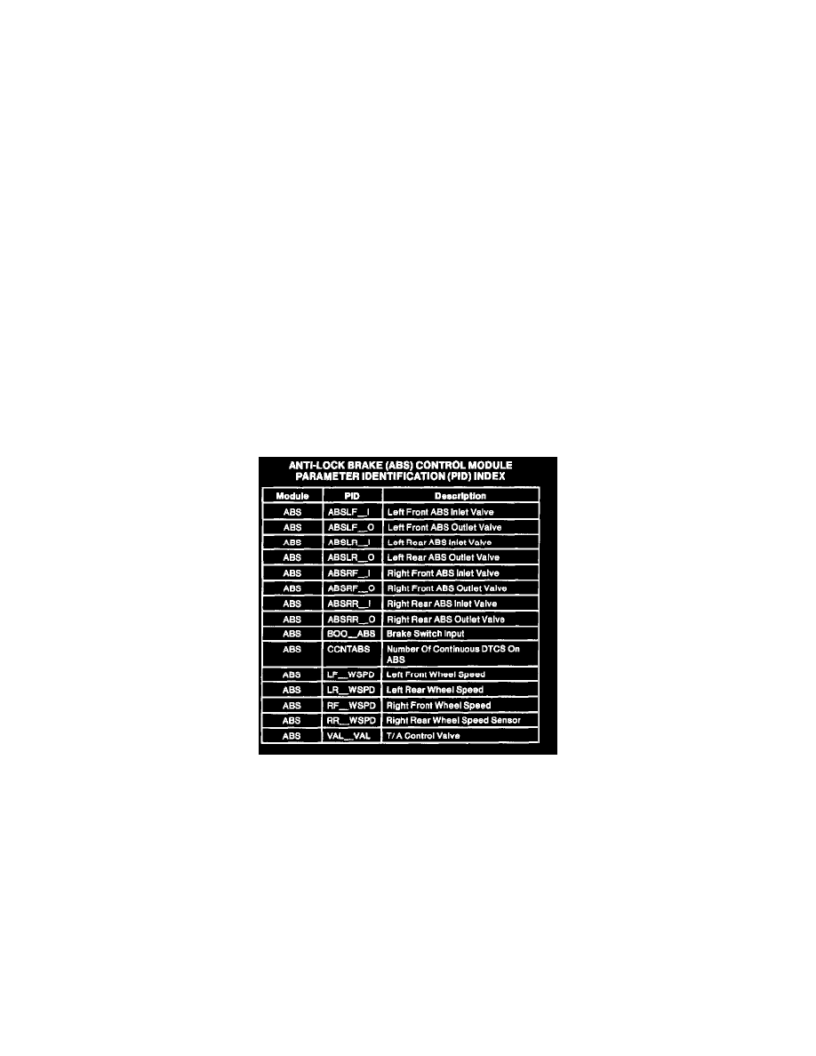
Antilock Brake PID Chart