
Crown Victoria V8-4.6L SOHC VIN 6 (1996)
Air Flow Meter/Sensor: Description and Operation
PURPOSE
The Mass Air Flow (MAF) sensor measures the amount of air flowing into the engine. This value is used by the Powertrain Control Module
(PCM) in calculating the required fuel injector pulsewidth in order to provide the desired air/fuel ratio. This input can also be used in determining
Electronic Pressure Control (EPC), shift, and torque converter clutch scheduling.
CONSTRUCTION
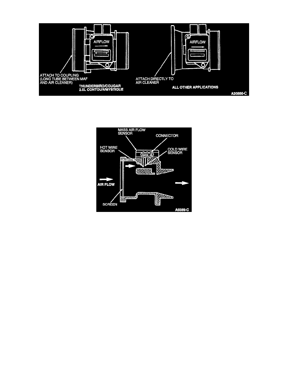
The MAF sensor is located directly in the air flow path between the air cleaner housing and the throttle body. All air entering the intake manifold
must pass through the sensor. Located in the MAF sensor directly in the airstream are two platinum wires, a hot wire heated by electrical current
and a cold reference wire. The MAF sensor uses the air flow across these wires to calculate its output.
OPERATION
The hot wire is maintained at 200°C (392°F) above ambient temperature as measured by a constant cold wire. The current required to maintain the
temperature of the hot wire is proportional to the air mass flow. The MAF sensor then measures the amount of electrical current required to
maintain this temperature difference and converts this value to an analog DC voltage. This output varies directly with the mass air flow rate.