
Crown Victoria V8-4.6L SOHC VIN 6 (1996)
Piston Assembly On Worm Shaft
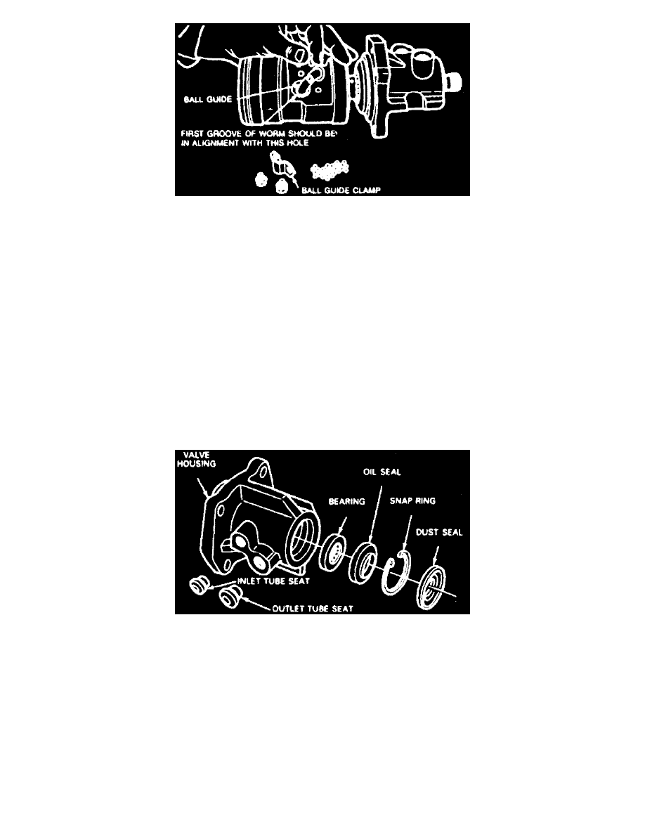
4. Place piston on bench with ball guide holes facing up. Insert worm shaft into piston so that first groove is in alignment with hole nearest to center
of piston.
5. Place ball guide into piston. Place balls in guide (27 minimum), turning worm clockwise (viewed from input end of shaft). If all balls have not
been fed into guide upon reaching right stop, rotate input shaft in one direction and then in the other while installing balls. After balls have been
installed, do not rotate input shaft or piston more than 3 1/2 turns off the right stop to prevent balls from falling out of circuit.
6. Securing guides to ball nut with clamp.
7. Apply petroleum jelly to piston seal.
8. Place a new O-ring on valve housing.
9. Slide piston and valve into gear housing, being careful not to damage seal.
10. Align lube passage in valve housing with one in gear housing, place O-ring in gear housing oil passage hole, then identification tag and install but
do not tighten attaching bolts at this time.
11. Rotate ball nut so that teeth are in same plane as sector teeth. Tighten valve housing attaching bolts to 30-45 ft lb.
12. Position sector shaft cover O-ring in gear housing. Turn input shaft as required to center piston.
13. Apply petroleum jelly to sector shaft journal, then position sector shaft and cover into gear housing. Install air conditioner line mounting bracket, if
equipped, and two sector shaft cover bolts, then tighten to 55-70 ft lb.
14. Attach an inch-pound torque wrench to input shaft and adjust mesh load.
Valve Housing
Exploded View Of Valve Housing
1. Using puller attachment T58L-101-B, or equivalent, remove and discard dust seal.
2. Remove snap ring from valve housing, then turn fixture so valve housing is upside down.
3. Install bearing remover T65P-3524-A2 and installer T65P-3524-A3, or equivalents to valve body opposite the oil seal, then gently tap bearing and
seal from housing. Discard seal. Exercise care when inserting and removing tool to prevent damage to valve bore in housing.
4. Remove oil inlet and outlet tube seats with rack bushing holding tool T74P-3504-L, or equivalent, if damaged.
5. Coat tube seats with petroleum jelly and position them in housing. Install and tighten tube nuts to press seats to proper location, using brass tube
seat replacer T74P-3504-M, or equivalent.
6. Coat bearing and seal surface in housing with a film of petroleum jelly.
7. Install bearing with metal side that covers rollers facing downward, then using bearing installer T65P-3524-A, or equivalent, seat bearing. Ensure
smooth bearing operation.
8. Dip new oil seal in power steering fluid, then place it in housing with metal side of seal facing outward. Drive seal into housing until outer edge of
seal does not quite clear snap ring.
9. Place snap ring in housing, then drive on ring until snap ring seats in its groove to locate seal properly.