
Crown Victoria V8-4.6L SOHC VIN 6 (1996)
Clutch: Service and Repair
Direct Clutch
DISASSEMBLE
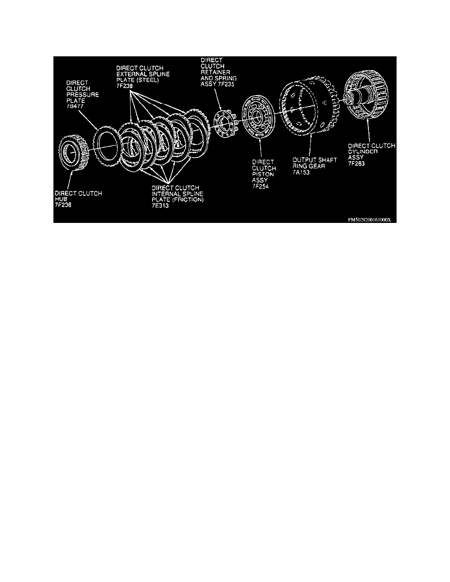
Exploded View Of Direct Clutch
1. Removing direct clutch hub, then the No. 7 bearing and bearing support.
2. Remove clutch pack snap ring, then the clutch pack. Note relation of clutch plates for assembly.
3. Using direct clutch spring compressor tool No. T81P-70235-A or equivalent, compress piston return spring, then remove piston retaining ring.
4. Remove spring retainer assembly and piston from cylinder. Use air pressure if necessary to remove clutch piston.
5. Remove inner seal from cylinder hub and outer seal from piston. Verify presence of check ball and that it moves freely.
ASSEMBLE
1. Install inner piston seal on clutch cylinder hub as follows:
a. Position direct clutch lip seal protector tool No. T80L-77234-A or equivalent over clutch cylinder hub. Lubricate seal and seal protector with
petroleum jelly.
b. Position seal over installer tool with sealing lip facing down.
2. Install clutch piston outer seal. Note direction of sealing lip before installation. Lip should point toward bottom of cylinder.
3. Install clutch piston as follows:
a. Coat inner and outer piston seals, clutch cylinder sealing area, and piston inner sealing area with petroleum jelly.
b. Position piston lip seal protector tool No. T80L-77254-A or equivalent in clutch drum and push piston to bottom of drum using even thumb
pressure.
4. Using direct clutch spring compressor tool No. T81P-70235-A or equivalent, install piston spring, retainer assembly, and retaining ring.
5. Install clutch pack.
6. With retaining ring installed, check clearance between ring and pressure plate using feeler gauge.
NOTE: Pressure plate should be held downward as clearance is checked.
a. Clearance should be 0.060-0.091 inch.
b. If clearance is not within limits, selective snap rings are available in the following thicknesses, 0.050-0.054 inch, 0.064-0.068 inch,
0.078-0.082 inch and 0.092-0.096 inch.
7. Install No. 7 needle bearing support and No. 7 needle bearing, black side up toward direct clutch hub.
8. Install direct clutch hub.