
Crown Victoria V8-4.6L SOHC VIN W (2005)
Driver/Vehicle Information Display: Initial Inspection and Diagnostic Overview
Principles of Operation
PRINCIPLES OF OPERATION
Electronic Cluster
The message center display is integral to the electronic instrument cluster. The instrument cluster receives the needed message center signals from the
fuel level sensor (part of the fuel pump module) and the powertrain control module (PCM). The message center information can be toggled by
pressing the appropriate message center switch. The message center display proves out along with the instrument cluster, when the ignition switch is
turned to the ON position. The message center then resumes the mode of operation last used. The message center displays are as follows:
-
average fuel economy (AVG ECON)
-
average speed (AVG SPEED)
-
distance to empty (DIST TO EMPTY)
-
instantaneous fuel economy (INST ECON)
-
trip distance A (TRIP A)
-
trip distance B (TRIP B)
Overhead Console
The message center module is located in the overhead console. The message center display is a green vacuum fluorescent, dot matrix display.
The message center display and switches are integral to the message center module. The message center displays the following normal modes:
-
compass
-
off
The MODE button will scroll through the normal modes.
The RESET button is used to acknowledge submenu options.
Inspection and Verification
INSPECTION AND VERIFICATION
1. Verify the customer concern.
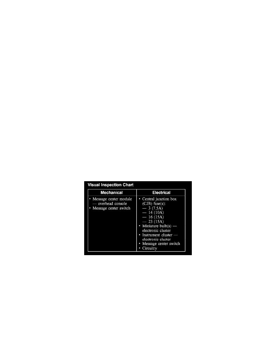
Visual Inspection Chart
2. Visually inspect for obvious signs of mechanical or electrical damage.
3. If an obvious cause for an observed or reported concern is found, correct the cause (if possible) before proceeding to the next step.
4. Verify that the following instrument cluster gauges are working correctly:
-
fuel level gauge
-
speedometer
5. If a gauge is not working correctly, refer to Instrument Cluster - Conventional or Instrument Cluster - Electronic. See: Instrument Panel, Gauges
and Warning Indicators/Testing and Inspection/Instrument Cluster - Conventional See: Instrument Panel, Gauges and Warning Indicators/Testing
and Inspection/Instrument Cluster - Electronic
6. If the cause is not visually evident, connect the diagnostic tool to the data link connector and select the vehicle to be tested from the diagnostic tool
menu. If the diagnostic tool does not communicate with the vehicle:
-
check that the program card is correctly installed.
-
check the connections to the vehicle.
-
check the ignition switch position.