
E 250 V8-5.4L (2008)
13. If equipped, remove the key-in-ignition warning indicator switch.
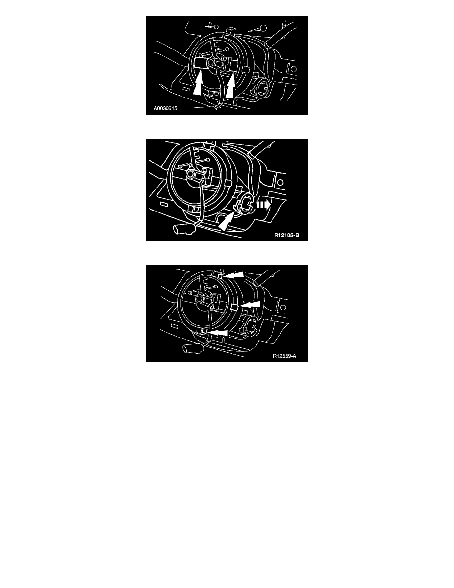
14. Release the 3 clockspring retaining clips.
15. Detach the 2 clockspring retaining clips holding the wire to the steering column.
16. Route the clockspring wiring through the instrument panel and remove the clockspring.
Installation
Vehicles installing a new clockspring
1. NOTE: A new clockspring is supplied in a centralized position and held there with a sealing key.
Remove the sealing key from the clockspring, holding the rotor in its centralized position.
-
Do not allow the clockspring rotor to turn.
Vehicles needing clockspring recentering
2. WARNING: If the clockspring is not correctly centralized, it may fail prematurely. If in doubt, repeat the centralizing procedure.
Failure to follow these instructions may increase the risk of serious personal injury or death in a crash.
CAUTION: To prevent damage to the clockspring, make sure the road wheels are in the straight-ahead position.
NOTE: The clockspring inner rotor, wiring and connector must be in the 12 o'clock position to install the steering wheel.
If the vehicle's clockspring has rotated out of center, follow these steps to center the clockspring.
1
Hold the clockspring outer housing stationary.