
E 350 V10-6.8L (2007)
MS-CAN Network Communication Fault Chart
The fault chart describes the specific MS-CAN network failures and their resulting symptom.
HS-CAN
The HS-CAN network uses an unshielded twisted pair cable of data (+) and data (-) circuits. The data (+) and the data (-) circuits are each regulated to
approximately 2.5 volts during neutral or rested network traffic. As bus messages are sent on the data (+) circuit, voltage is increased by
approximately 1.0 volt. Inversely, the data (-) circuit is reduced by approximately 1.0 volt when a bus message is sent. Multiple bus messages can
be sent over the network CAN circuits allowing multiple modules to communicate with each other and designed for real time information transfer and
control. The HS-CAN network will not communicate while certain faults are present, but will operate with diminished performance with other faults
present. The HS-CAN bus may remain operational when 1 of the 2 termination resistors are not present.
The HS-CAN network operates at a maximum data transfer speed of 500 Kbps and is designed for real time information transfer and control. The
network will remain operational, but at a degraded level when certain circuit faults are present. The HS-CAN network may remain operational with
only one termination resistor present.
The following modules are on the HS-CAN network.
-
Powertrain control module (PCM)
-
Anti-lock brake system (ABS) module (with roll stability control) (if equipped)
-
Instrument cluster
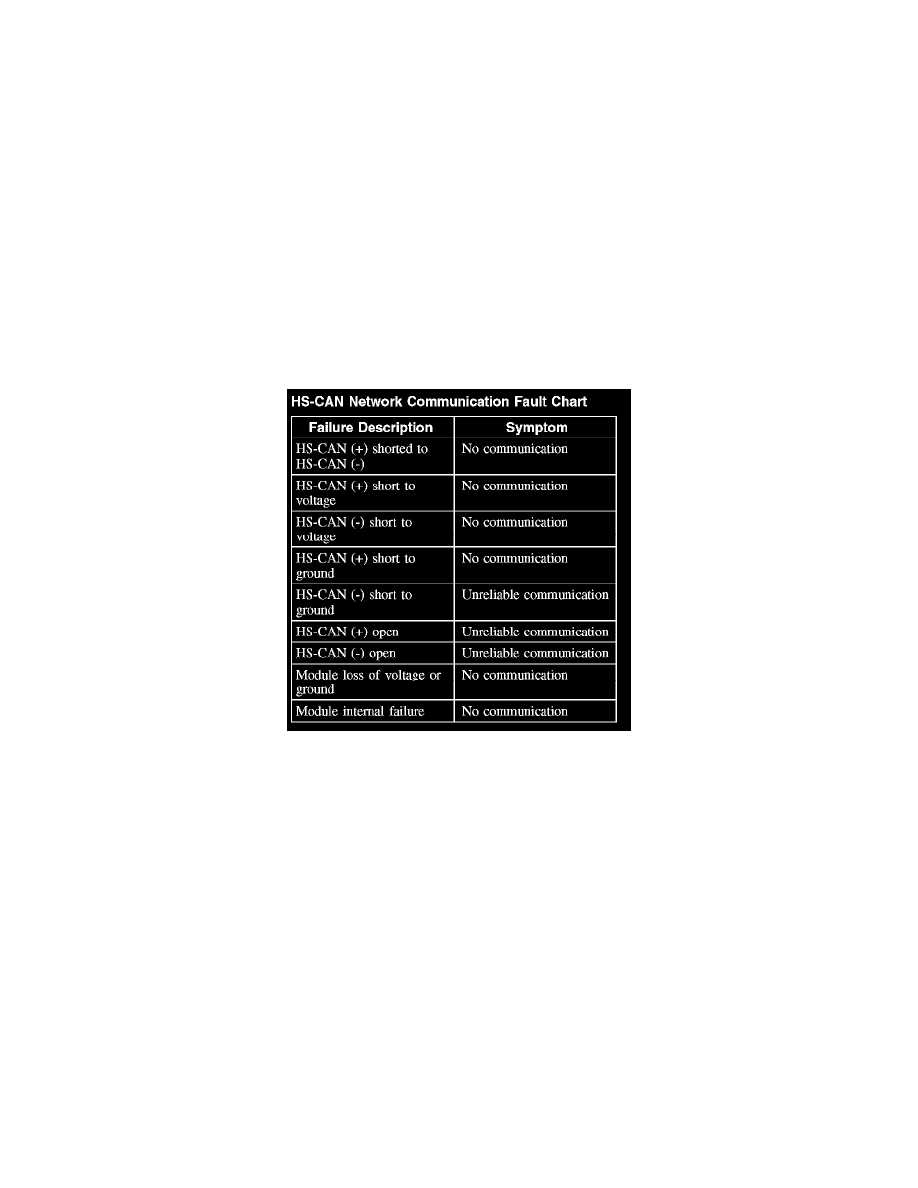
HS-CAN Network Communication Fault Chart
The fault chart describes the specific HS-CAN network failures and their resulting symptom.