
E 350 V8-6.0L DSL Turbo (2007)
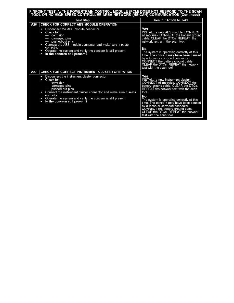
A26-A27
Normal Operation
The PCM communicates with the scan tool through the HS-CAN. Circuits 1827 (WH/LG) (HS-CAN +) and 1828 (PK/LG) (HS-CAN -) provide the
network connection to the PCM. The PCM shares the HS-CAN network with the anti-lock brake system (ABS) with roll stability control module (if
equipped), and the instrument cluster. Voltage for the PCM is provided by circuits 361 (RD) and 3049 (BK/LG). Circuits 570 (BK/WH) and 875
(BK/LB) provide ground.
Possible Causes
-
Fuse
-
Circuit 361 (RD) open
-
Circuit 570 (BK/WH) open
-
Circuit 875 (BK/LB) open
-
Circuit 1827 (WH/LG) open, short to ground or voltage (HS-CAN +)
-
Circuit 1828 (PK/LG) open, short to ground or voltage (HS-CAN -)
-
Circuit 1827 (WH/LG) (HS-CAN +) and circuit 1828 (PK/LG) (HS-CAN -) shorted together
-
Circuit 3049 (BK/LG) open
-
PCM
-
Instrument cluster
-
ABS module with roll stability control (if equipped)
Test B: The Anti-Lock Brake System (ABS) Module With Roll Stability Control Does Not Respond to
the Scan Tool
PINPOINT TEST B: THE ANTI-LOCK BRAKE SYSTEM (ABS) MODULE WITH ROLL STABILITY CONTROL DOES NOT RESPOND
TO THE SCAN TOOL