E 450 V10-6.8L (2008)

Component Referencing (4)
Components on a diagram have a reference to a component location view or the diagram where it is shown completely. The reference is located to the
right of each component.
Component Names (5)
Component names are placed on the right hand side of each component when possible. Descriptions of the internals of the component are also
included when available. The diagram where the component appears in full is listed in the Index. The base part number for a component is listed in
parentheses next to or under a component.
Internal Name and Function Identification Numbers (6)
Some components on each diagram have internal symbols with an identification number located within it. You can identify the internal symbol or
function by finding the corresponding number under the component name.
Circuit Numbering and Wire Identification (7)
Ford Motor Company uses three different circuit numbering conventions: Standard Circuit Numbering System, Global Circuit Numbering System, and
New Global Circuit Numbering System (NGCNS). With each, the circuit number (which identifies a specific circuit function) is followed by the wire
color.
The wire identification consists of a basic color and possibly a stripe, and is determined directly from the wire's circuit number. In the diagrams, the
wire colors are indicated next to the wires. The colors are abbreviated using the international norm IEC 757. The abbreviations are listed in set 4
"Symbols".
Fuse and Relay Information
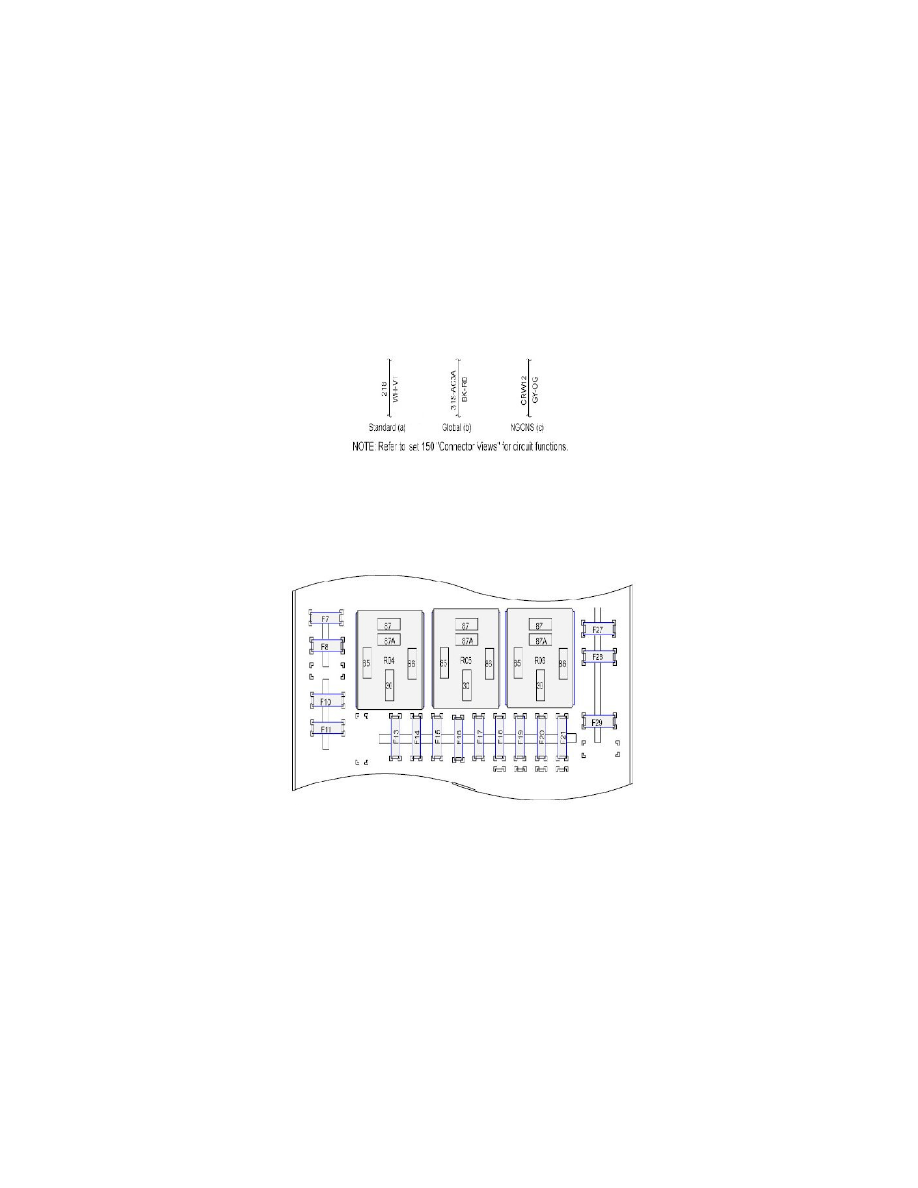
Fuse/Locations and Relay/Locations contains a view of the fuse/relay box, in which all fuses and relays are identified. Fuse and Relay Numbering and
Naming. Fuse and relay numbering and naming follow the indication of the fuse panel cover. In addition, for all removable relays, pin positions are
added to illustrate proper orientation.
Power Distribution
