
E 450 V8-5.4L (2009)
has been previously drained. Following these instructions will help prevent system contamination, brake component damage and the risk of serious
personal injury.
WARNING: Carefully read cautionary information on product label. For EMERGENCY MEDICAL INFORMATION seek medical advice.
For additional information, consult the product Material Safety Data Sheet (MSDS) if available. Failure to follow these instructions may result
in serious personal injury.
NOTICE: Do not spill brake fluid on painted or plastic surfaces or damage to the surface may occur. If brake fluid is spilled onto a painted or
plastic surface, immediately wash the surface with water.
Vehicles equipped with 6.0L engines or Hydro-Boost(R)
1. Remove the upper air deflector.
2. Remove the Air Cleaner (ACL) assembly.
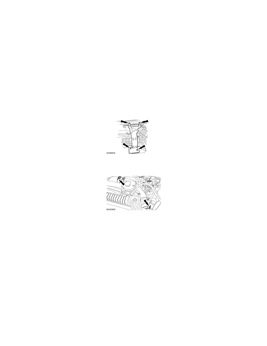
3. NOTE: Do not disconnect the hoses from the power steering reservoir.
Remove the 4 bolts and position the power steering fluid reservoir and bracket aside.
-
To install, tighten the bolts to 28 Nm (21 lb-ft).
4. Loosen the clamps and remove the Charge Air Cooler (CAC) pipe.
-
To install, tighten clamps to 12 Nm (106 lb-in).
All vehicles
5. Remove the master cylinder primary and secondary brake tubes.
-
To install, tighten brake tube fittings on vehicles equipped with standard ABS to 18 Nm (159 lb-in).
-
To install, tighten brake tube fittings on vehicles equipped with Roll Stability Control (RSC(R)) to 28 Nm (21 lb-ft).
6. NOTE: Plug each port of the Hydraulic Control Unit (HCU) to prevent brake fluid from spilling.
Disconnect the 3 brake caliper-to-HCU tube fittings.
-
To install, tighten fittings on vehicles equipped with standard ABS to 18 Nm (159 lb-in).
-
To install, tighten fittings on vehicles equipped with RSC(R) to 28 Nm (21 lb-ft).
7. Release the brake tube clip from the HCU bracket and position the brake tubes aside.
8. Disconnect the ABS module electrical connector.
9. Remove the 3 HCU bracket-to-inner fender well nuts and remove the HCU assembly.
-
To install, tighten to 29 Nm (21 lb-ft).
10. To install, reverse the removal procedure.
-
Bleed the brake system.