
E 450 V8-5.4L (2009)
Timing Chain: Diagrams
NOTICE: Timing chain procedures must be followed exactly or damage to valves and pistons will result.
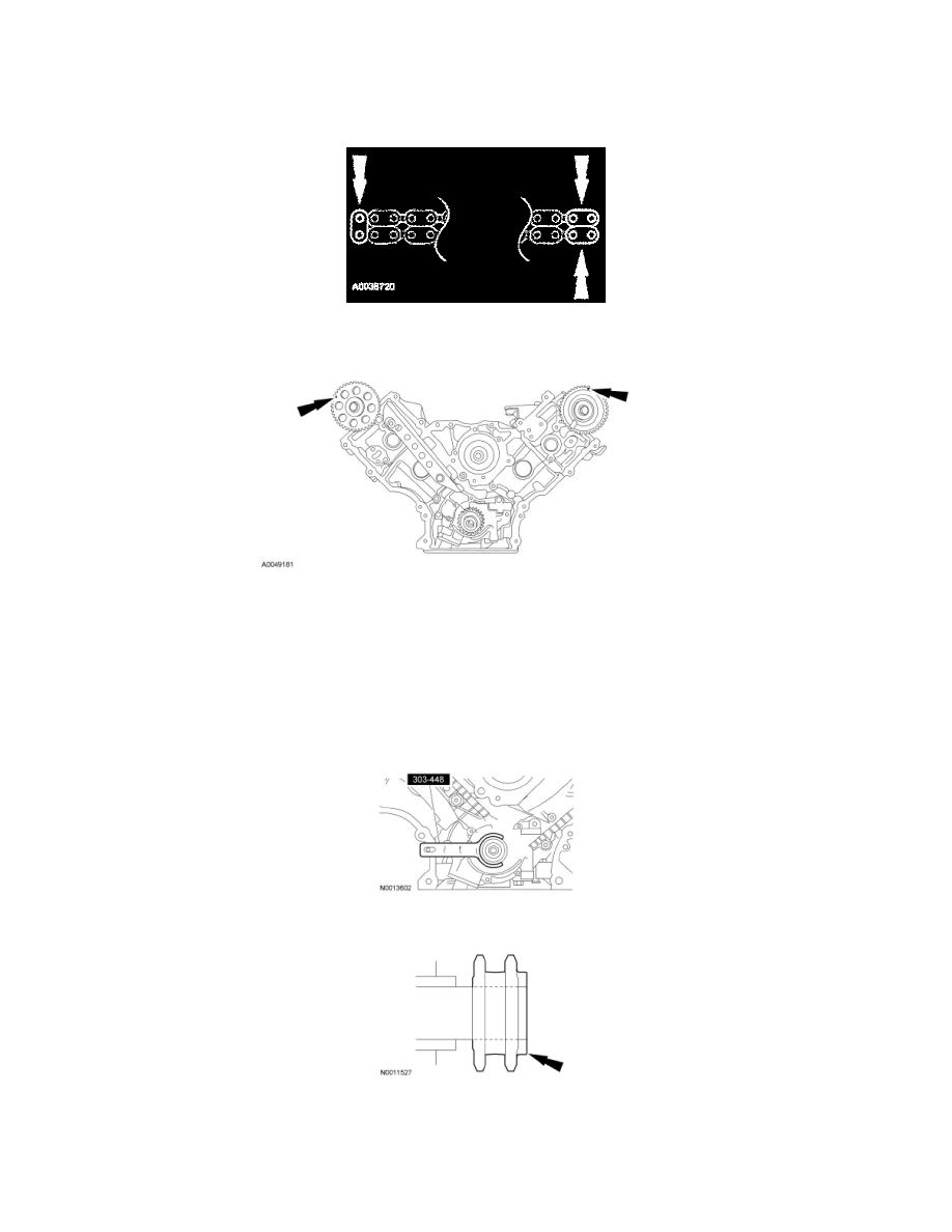
If the copper links are not visible, mark 2 links on one end and 1 link on the other end, and use as timing marks.
Rotate the RH camshaft sprocket until the timing mark is approximately at the 11 o'clock position. Rotate the LH camshaft sprocket until the timing mark
is approximately at the 12 o'clock position.
NOTICE: Unless otherwise instructed, at no time when the timing chains are removed and the cylinder heads are installed is the crankshaft or
camshaft to be rotated. Severe piston and valve damage will occur.
NOTICE: Rotate the crankshaft counterclockwise only. Do not rotate past position shown or severe piston and valve damage can occur.
NOTE: The No. 1 cylinder is at Top Dead Center (TDC) when the stud on the engine block fits into the slot in the handle of the Crankshaft Holding
Tool.
Position the crankshaft so the No. 1 cylinder is at TDC with the Crankshaft Holding Tool.
Install the crankshaft sprocket, making sure the flange faces forward.
Position the lower end of the LH (inner) timing chain on the crankshaft sprocket, aligning the timing mark on the outer flange of the crankshaft sprocket
with the single copper (marked) link on the chain.