
E 450 V8-5.4L (2009)
-
Is the voltage greater than 10 volts?
Yes
GO to H18.
No
GO to H19.
-------------------------------------------------
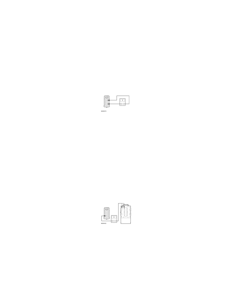
H18 CHECK FOR VOLTAGE TO THE REAR STOPLAMP USING THE GROUND PIN
-
While applying the brake pedal, measure the voltage between the LH rear lamp C4035-3, circuit CLS18 (GY/BN), harness side and the LH rear
lamp C4035-1, circuit GD149 (BK/GY), harness side; or between the RH rear lamp C4032-3, circuit CLS19 (VT/OG), harness side and the RH
rear lamp C4032-1, circuit GD149 (BK/GY), harness side.
-
Is the voltage greater than 10 volts?
Yes
INSTALL a new bulb holder. CLEAR the DTCs. REPEAT the self-test.
No
REPAIR circuit GD149 (BK/GY) for an open. CLEAR the DTCs. REPEAT the self-test.
-------------------------------------------------
H19 CHECK THE STOPLAMP OUTPUT CIRCUIT FOR AN OPEN
-
Disconnect: SJB C2280d.
-
Measure the resistance between the LH rear lamp C4035-3, circuit CLS18 (GY/BN), harness side and the SJB C2280d-25, circuit CLS18
(GY/BN), harness side; or between the RH rear lamp C4032-3, circuit CLS19 (VT/OG), harness side and the SJB C2280d-26, circuit CLS19
(VT/OG), harness side.
-
Is the resistance less than 5 ohms?
Yes
GO to H22.
No
REPAIR the circuit. CLEAR the DTCs. REPEAT the self-test.
-------------------------------------------------
H20 ISOLATE THE BULB HOLDER AS THE CAUSE OF THE CIRCUIT SHORT