
E 450 V8-5.4L (2009)
-
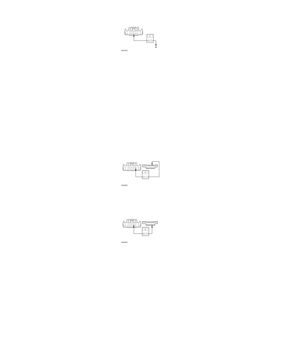
For vehicles not equipped with a telematics module, measure the resistance between the TBC module C2124-11, circuit GD116 (BK/VT), harness
side and ground.
-
Is the resistance less than 5 ohms?
Yes
GO to E3.
No
REPAIR the circuit. CONNECT the negative battery cable. CLEAR the DTCs. REPEAT the network test with the scan tool.
-------------------------------------------------
E3 CHECK THE HS-CAN CIRCUITS BETWEEN THE TBC MODULE AND THE DLC FOR AN OPEN
-
For vehicles equipped with a telematics module, measure the resistance between the TBC module C2142-2, circuit VDB04 (WH/BU), harness side
and the Data Link Connector (DLC) C251-6, circuit HSC1-A (WH/BU), harness side.
-
For vehicles not equipped with a telematics module, measure the resistance between the TBC module C2142-2, circuit VDB04 (WH/BU), harness
side and the DLC C251-6, circuit VDB04 (WH/BU), harness side.
-
For vehicles equipped with a telematics module, measure the resistance between the TBC module C2142-3, circuit VDB05 (WH), harness side
and the DLC C251-14, circuit HSC2-A (WH), harness side.
-
For vehicles not equipped with a telematics module, measure the resistance between the TBC module C2142-3, circuit VDB05 (WH), harness side
and the DLC C251-14, circuit VDB05 (WH), harness side.
-
Are the resistances less than 5 ohms?
Yes
CONNECT the negative battery cable. GO to E4.
No
REPAIR the circuit in question. CONNECT the negative battery cable. REPEAT the network test with the scan tool.
-------------------------------------------------
E4 CHECK FOR CORRECT TBC MODULE OPERATION
-
Disconnect all the TBC module connectors.
-
Check for:
-
corrosion
-
damaged pins
-
pushed-out pins