
E 450 V8-5.4L (2009)
-
Wiring, terminals or connectors
-
ACM
PINPOINT TEST G: THE ACM DOES NOT RESPOND TO THE SCAN TOOL
NOTICE: Use the correct probe adapter(s) when making measurements. Failure to use the correct probe adapter(s) may damage the
connector.
NOTE: Failure to disconnect the battery when instructed will result in false resistance readings. Refer to Battery.
-------------------------------------------------
G1 CHECK THE ACM VOLTAGE SUPPLY CIRCUITS FOR AN OPEN
-
Ignition OFF.
-
Disconnect: ACM C290a.
-
Ignition ON.
-
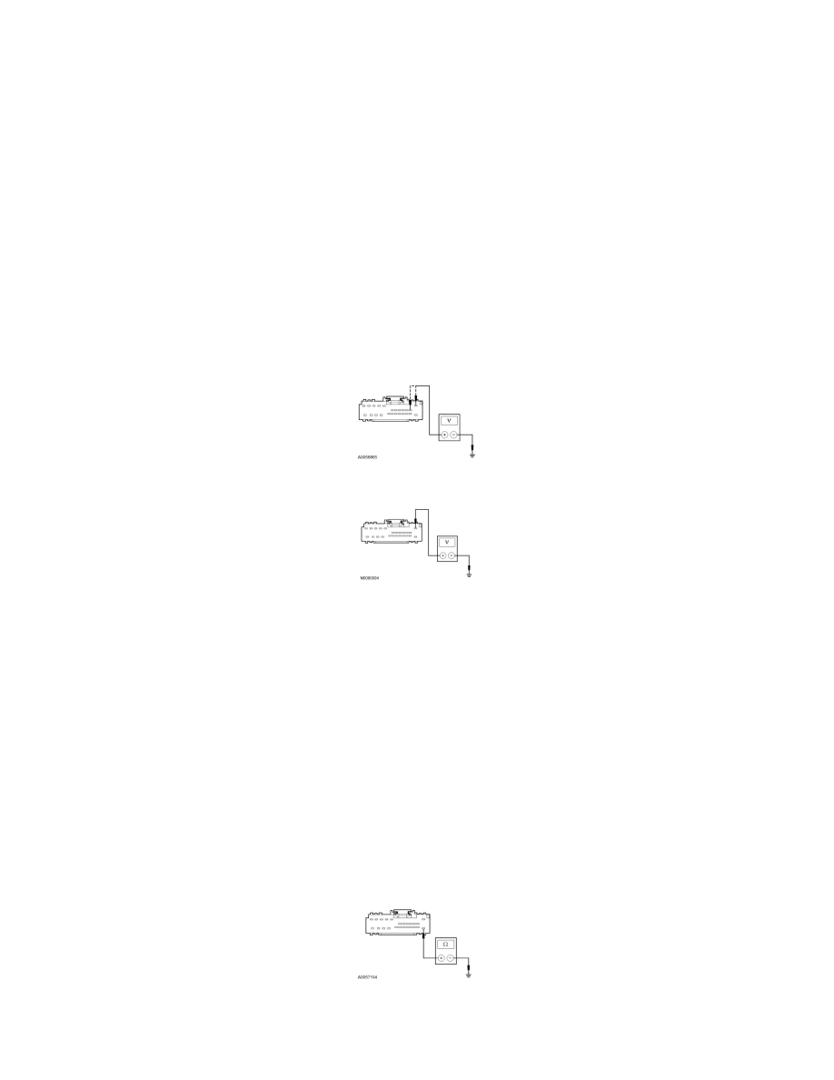
For non-navigation ACM equipped vehicles, measure the voltage between the ACM C240a-1, circuit SBP39 (WH/RD), harness side and ground;
and between the ACM C240a-2, circuit CPB41 (BU), harness side and ground.
-
For navigation ACM equipped vehicles, measure the voltage between the ACM C240a-1, circuit SBP39 (WH/RD), harness side and ground.
-
Are the voltages greater than 10 volts?
Yes
GO to G2.
No
VERIFY the Smart Junction Box (SJB) fuse 39 (20A) or 41 (15A) is OK. If OK, REPAIR the circuit in question. If not OK, REFER to the Wiring
Diagrams to identify the possible causes of the circuit short. CLEAR the DTCs. REPEAT the network test with the scan tool.
-------------------------------------------------
G2 CHECK THE ACM GROUND CIRCUIT FOR AN OPEN
-
Ignition OFF.
-
Disconnect: Negative Battery Cable.
-
Measure the resistance between the ACM C240a-13, circuit GD115 (BK/GY), harness side and ground.
-
Is the resistance less than 5 ohms?
Yes