
E 450 V8-5.4L (2009)
-------------------------------------------------
K12 CHECK THE HS-CAN (+) AND HS-CAN (-) CIRCUITS FOR A SHORT TOGETHER
WITH THE TELEMATICS MODULE DISCONNECTED
-
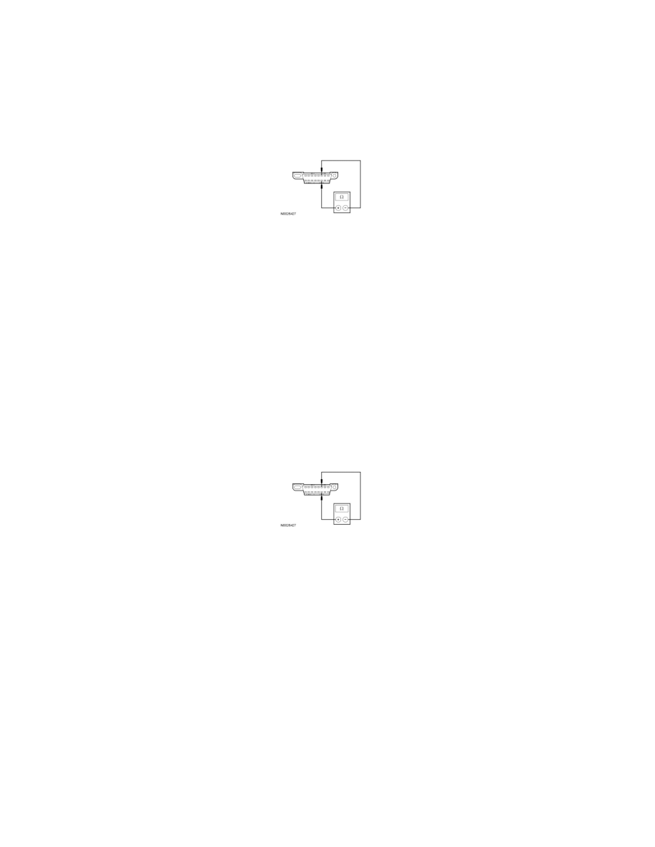
Disconnect: Telematics Module C2409.
-
Measure the resistance between the DLC C251-6, circuit VDB04 (WH/BU), harness side and the DLC C251-14, circuit VDB05 (WH), harness
side.
-
Is the resistance less than 5 ohms?
Yes
GO to K13.
No
CONNECT the negative battery cable. GO to K28.
-------------------------------------------------
K13 CHECK THE HS-CAN (+) AND HS-CAN (-) CIRCUITS FOR A SHORT TOGETHER
WITH THE ABS MODULE DISCONNECTED
-
Disconnect: ABS Module C135 or C155.
-
Measure the resistance between the DLC C251-6, circuit VDB04 (WH/BU), harness side and the DLC C251-14, circuit VDB05 (WH), harness
side.
-
Is the resistance less than 5 ohms?
Yes
For stripped chassis, GO to K16.
Otherwise, GO to K14.
No
CONNECT all modules. CONNECT the negative battery cable. GO to K24.
-------------------------------------------------
K14 CHECK THE HS-CAN (+) AND HS-CAN (-) CIRCUITS FOR A SHORT TOGETHER
WITH THE RCM DISCONNECTED
-
Disconnect: Restraints Control Module (RCM) C310b.
-
Measure the resistance between the DLC C251-6, circuit VDB04 (WH/BU), harness side and the DLC C251-14, circuit VDB05 (WH), harness
side.