
E 450 V8-5.4L (2009)
Alignment: Service and Repair
Camber and Caster Adjustment
Camber and Caster Adjustment
1. Using alignment equipment and the manufacturer's instructions, measure the caster and camber.
-
Refer to Alignment Specifications in the Specifications portion for optimal alignment settings.
-
If the caster and camber values are not within specification, go to the next step.
2. Remove and discard the upper ball joint pinch bolt.
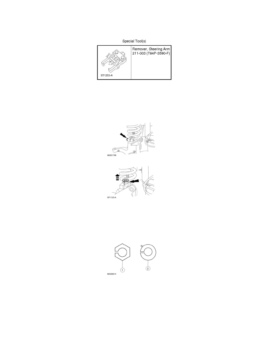
3. Remove the existing adjuster sleeves. All vehicles are built by the assembly plant with a non-adjustable camber/caster sleeve.
1. Service adjusters have a 6-sided flange with the camber/caster adjustment range stamped into the top (0 degree, 1/4 degree, 1/2 degree, 3/4
degree or 1 degree, 1-1/4 degree and 1-1/2 degree).
2. Production adjusters have a round flange with a side tab. The amounts of pre-set camber and caster are stamped into the top of the adjuster.
4. NOTICE: Do not allow the camber adjustment sleeve to contact the ball joint seal when installing a sleeve or damage to the ball joint seal
may occur. Allow for a minimum of 2 mm (0.079 in) clearance between the camber adjustment sleeve and the ball joint seal.
Install interim 0 degree service adjusters to both sides of the vehicle.
5. Install the upper ball joint pinch bolt.
-
Tighten to 103 Nm (76 lb-ft).
6. Install the front wheel(s) and check caster and camber readings with the 0 degree service adjusters installed.
7. Calculate the maximum amount of camber and/or caster adjustment required to achieve the optimal settings, as provided in the Alignment