
E 450 V8-5.4L (2009)
-
Discard the cotter pin.
-
To install, tighten to 90 Nm (66 lb-ft).
7. Using the Steering Arm Remover, separate the sector shaft arm drag link from the sector shaft arm and remove the drag link.
8. NOTE: For reference during installation, count and record the number of turns required to separate the outer tie-rod end and adjusting sleeve from
the sector shaft arm drag link.
Loosen the RH outer tie-rod end adjusting sleeve clamp nut and separate the outer tie-rod end and adjusting sleeve from the sector shaft arm drag
link.
-
To install, tighten to 55 Nm (41 lb-ft).
9. NOTE: When installing the steering linkage damper-to-drag link bracket, make sure the bracket is correctly positioned on the sector shaft arm
drag link before tightening the U-bolt nuts.
If equipped, remove the 4 steering linkage damper-to-drag link bracket U-bolt nuts, U-bolts and bracket.
-
To install, tighten to 31 Nm (23 lb-ft).
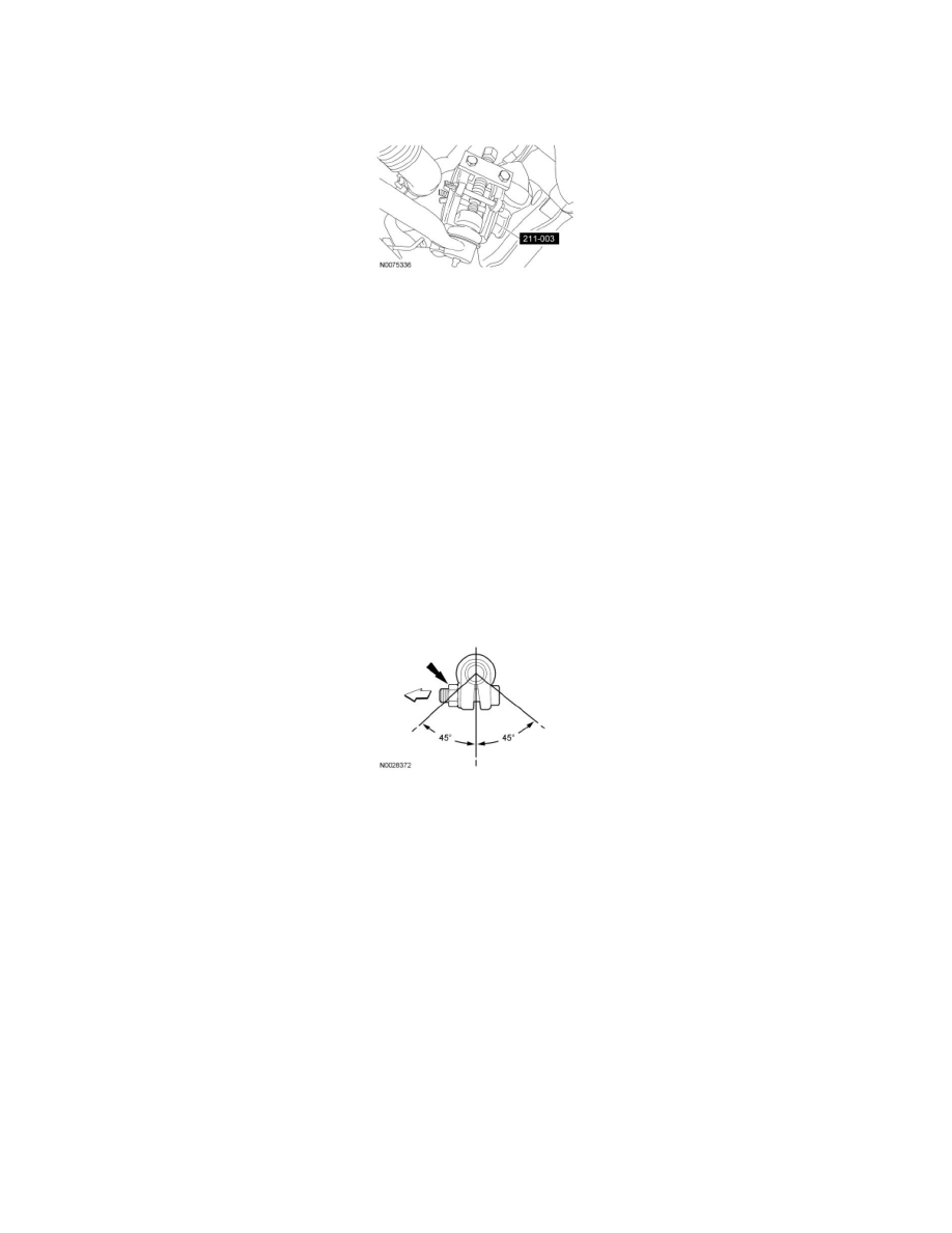
10. NOTE: When tightened, the adjusting sleeve bolts, nuts and clamps must be positioned within 45 degrees (±) of vertical. The threaded ends of the
adjusting sleeve bolts should point towards the front of the vehicle.
Position both adjusting sleeve clamp openings downward within 45 degrees of vertical.
11. To install, reverse the removal procedure.
-
Install new cotter pins.
12. Check and, if necessary, adjust the front toe.