
Econoline E350 1 Ton V8-5.4L Prop SOHC VIN Z (1998)
10.
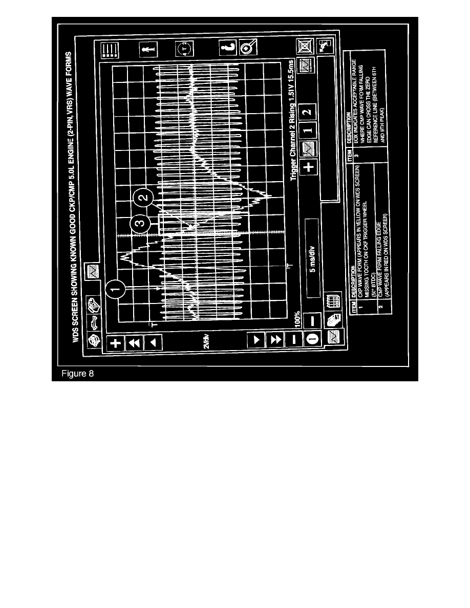
Press the start button and view both the CKP sensor as well as the CMP sensor signals. Figures 6, 7 and 8).
11.
Compare the wave forms of both sensors.
^
The missing tooth of the CKP sensor trigger wheel will be shown on the screen as an extra space between the wave forms. This position is 60°
Before Top Dead Center (BTDC)
^
The upper peaks of the wave form are each spaced 10° of crankshaft rotation apart
^
The CMP timing setting on all current 6-cylinder engines should be between 10 and 40° After Top Dead Center (ATDC)
On all Hall-effect sensors, the CMP wave form rising edge should occur between the 7th and the 10th peak past the missing tooth. (Figure 6)
On the VRS sensors (except 5.0L engines), the falling edge of the CMP waveform should cross the zero reference line between the 7th and 10th peak
past the missing tooth waveform. (Figure 7).
On 5.0L engines With a VRS CMP sensor, the falling edge waveform should cross the zero reference line between the 6th and the 9th peak past the CKP
missing tooth (Figure 8).
On 5.0L engines with a Hall-effect VRS CMP sensor, the rising edge of the wave form should occur between the 6th and 9th peak past the CKP missing
tooth wave form.
(CMP) SYNCHRONIZER INSTALLATION PROCEDURE