
Econoline E350 1 Ton V8-5.4L Prop SOHC VIN Z (1998)
Information Bus: Initial Inspection and Diagnostic Overview
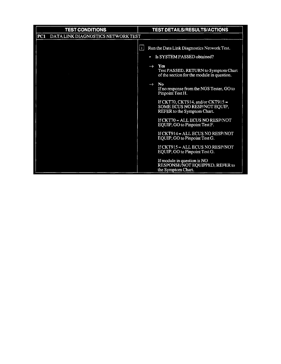
PC1
Inspection and Verification
1. Verify the customer concern.
2. Visually inspect the following for obvious signs of electrical damage:
VISUAL INSPECTION CHART
Electrical
-
Fuses
-
Damaged wiring harness
-
Loose or corroded connectors
-
4-wheel anti-lock brake control module
-
Electronic Crash Sensor (ECS) module
-
Powertrain Control Module (PCM)
-
Natural Gas Vehicle Module (NGVM)
-
Auxiliary Powertrain Control Module (APCM)
3. If the concern remains after the inspection, connect the New Generation STAR (NGS) Tester to the Data Link Connector (DLC) located beneath
the instrument panel and select the vehicle to be tested from the NGS Tester menu. If the NGS Tester does not communicate with the vehicle:
-
check that the program card is properly installed.
-
check the connections to the vehicle.
-
check the ignition switch position.
If the NGS still does not communicate with the vehicle, go to Pinpoint Test H. See: Pinpoint Tests/H: No Module/Network Communication
4. Go to Pinpoint Test PC. See: System Precheck