
Econoline E350 1 Ton V8-5.4L Prop SOHC VIN Z (1998)
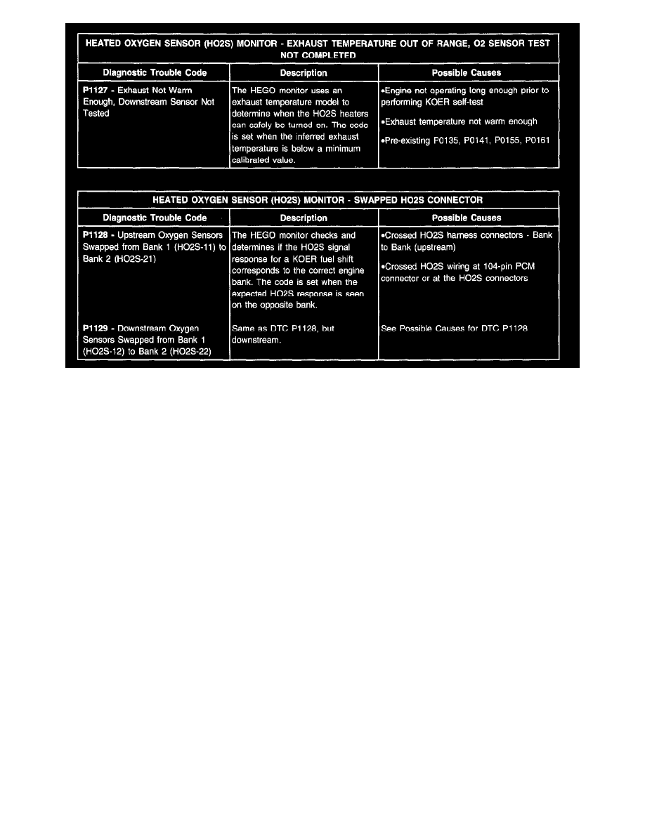
C2.) Heated Oxygen Sensor (HO2S) Monitor - Diagnostic Trouble Codes
D. Catalyst Efficiency Monitor
D1.) Catalyst Efficiency Monitor - Information
The Federal Test Procedure Catalyst Monitor monitors for deterioration in the catalyst system and illuminates the MIL when tailpipe emissions exceed
the appropriate HC emission thresholds. The Catalyst Monitor is enabled after the upstream and downstream HO2S sensors have been tested and verified
to be functional. This monitor relies on the front and rear heated oxygen sensors (HO2S) to infer catalyst efficiency based upon oxygen storage capacity.
Under normal closed loop fuel conditions, high efficiency catalysts have oxygen storage which makes the switching frequency of the rear HO2S quite
slow compared with the frequency of the front HO2S. As catalyst efficiency deteriorates, its ability to store oxygen declines, and the rear HO2S begins to
switch more rapidly, approaching the frequency of the front sensor. In general, as catalyst efficiency decreases, the switch ratio increases from a switch
ratio of 0 for a low mileage catalyst to a switch ratio of 0.8 or 0.9 for a low efficiency catalyst.
Some vehicles will monitor substantially less than the entire catalyst volume in order to meet the stringent catalyst monitoring malfunction thresholds. In
many cases, only the front, light-off catalyst is monitored.
Front and rear HO2S switches are counted under specified closed loop fuel conditions. After the required number of front switches are obtained, a
rear-to-front HO2S switch ratio is calculated. The switch ratio is compared against a threshold value. If the switch ratio is greater than the calibrated
maximum limit, the catalyst has failed. The test entry conditions for the Catalyst Efficiency Monitor are as follows: ECT or CHT (warmed engine), IAT
(not at extreme ambient temperatures), MAF (greater than minimum engine load), VSS (within vehicle speed window) and TP (at part throttle) are
required.
^
Because an exponentially weighted moving average is used for malfunction determination, up to six OBD II drive cycles may be required to
illuminate the MIL.
NOTE
THE CATALYST MONITOR ON SOME EARLY OBD II VEHICLES (SOME 1994-1996 VEHICLES) WAS REFERRED TO AS THE
"STEADY-STATE CATALYST MONITOR" AS OPPOSED TO THE "FTP CATALYST MONITOR" (DESCRIBED ABOVE) THAT IS MOST
COMMON FOR VEHICLES BUILT AFTER 1996. BELOW IS A BRIEF DESCRIPTION OF THE STEADY-STATE CATALYST MONITOR:
The Steady-State Catalyst Monitor performs a 20 second test during steady state rpm and load conditions. The Monitor transfers closed loop fuel control
from the front to the rear 02 sensors. The Monitor then observes the switching frequency and compares it to a threshold frequency stored in an rpm/load
table. A frequency higher than the maximum calibrated threshold indicates a malfunction.
The Catalyst Monitor DTCs can be categorized as follows: